Re-Engineered Airlock Breathes New Life into Operations & Budget
April 21, 2015

There is little more frustrating than having to pour time and resources into an Achilles’ heel of a pneumatic system that does not improve over time. Imagine having to replace two airlocks every 30 days just to avoid substantial losses in production.
This was the case more than two years ago with a prominent calcium carbonate producer located in the Midwest. Running 24/7, the application moved 1.5 tn/hr of calcium carbonate (160°F) through two airlocks, into a 5-in. positive pressure pneumatic line rated at 10 psi. The airlocks were 10-in. cast iron, drop-through style. Each was equipped with an 8-vane, mild steel closed-end rotor with replaceable wear strips (non-beveled). Hard chrome (.002 in.) was applied to the housing for wear resistance.
At 160°F, the clearance between the rotor and the housing was set at .006-.009 in. In the past, the clearances were set tighter in an attempt to get longer life from the airlocks by delaying the inevitable blow by that would occur. This, however, was found to be too tight, causing the rotor to engage the housing. Once the product opened up the clearance to .011 in. or more, the blow by became too excessive for the application.
Due to the abrasive nature of the calcium carbonate containing small particles of ceramic, the units would open up .002-.005 in. within a matter of a month’s run time. Maintaining the correct clearance in this application is crucial. If left in line longer than 30 days, the blow by through the airlocks would be enough to change the matrix of the product being conveyed. The coarser material would suspend under the sifter, and work its way back into the fines system, causing the product to become out of spec. If this occurred, the entire bin the product was transferred to would need to be scrapped, and cleaned out. This translated into a $100,000 loss in product alone. Thus, the lesser of the two evils was to spend approximately $10,090/month (equipment, labor, and lost production) changing out two airlocks on a routine basis.
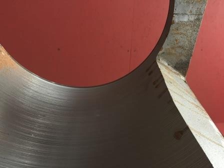
At the end of a month, the typical wear exhibited on the airlock was most evident at the bottom of the housing inlet where the rotor vanes met the housing, as well as the i.d. of the housing where the product was transferred. The o.d. of the rotor showed the most wear on the shrouds. The combination of an extremely abrasive material and slightly higher line pressures quickly allowed the chrome plating to fail and open up the clearances. The increasing clearances, then, only accelerated with the sandblast-like airflow through the airlock.
After a thorough examination of the effect the application had on the airlocks with Rotary Airlock, a proposed solution was offered, starting with a ceramic coating (.010 in.) on the i.d. of the housing for greater wear resistance. The concern, however, was the vulnerability of the inlet edge where the rotor vanes meet the housing. Wear on the inlet above the coating could diminish, allowing the ceramic coating to start to come off. To address this potential problem, a bead of facing wire was applied at the edge of the inlet to protect the ceramic. Due to the lack of wear found in the actual throat of the housing, added protection of the entire inlet was determined to not be necessary.
A new rotor was constructed entirely of AR500 metal to strengthen both the o.d. of the shrouds and the vanes. The vanes were also canted and beveled at the tips to ease each vane into the inlet. The theory was that the shearing action would help reduce the potential for product jamming at the pinch point of the vanes and housing. A reduction in the vane tip surface was speculated to reduce the amount of product being dragged through the housing as a squared vane tip would create.
After the trial airlock was re-engineered and remanufactured, it was placed into service in October of 2012 alongside the second airlock being brand new. As a precautionary measure, both airlocks would be pulled from service every 30 days to assess the damage that may have occurred. The goal was to have the re-engineered airlock last at least six months.
In November, both units were pulled for evaluation. The new airlock displayed the expected wear, and was removed from service. The trial unit showed no wear at the inlet, and the clearances of .006-.009 in. were still intact. The December and January intervals were found to be just as successful. Since very little wear was found on the trial lock, it was determined to check the airlock in six months.
With nine months of service already realized, the airlock was checked again in July of 2013. The wear points still were intact, and the clearances showed little indication of opening up, to the point another six-month check was justified. In January of 2014, the clearances were starting to open up a couple of thousandths in some spots, but since the integrity of the fines was still within spec, it was re-installed to be checked again within two to three months.
In March of 2014, the trial airlock was pulled from service as a precaution. The clearances had opened sufficiently enough to where the .011-in. threshold was drawing near. The facing wire on the inlet showed little wear, but had more importantly, protected the ceramic coating as intended. This additional barrier appears to have been the key to preventing the rest of the housing from wearing sooner rather than later.
Most of the wear occurred evenly on the rotor, not focused just on the shrouds. Because the beveled vane tips had not worn as quickly as the original wear strips, the results tended to support the theory that a reduction in the vane tip surface reduced the amount of drag in the housing. Further tests such as going back to a squared vane with the current modifications would help make this theory more conclusive.
The longer run time in production also allowed for significant financial gains. Under the operations with the original airlock set up for just one airlock, the cost for 17 months was $84,300 (17 airlocks, labor, and lost production). Had the production line not been stopped for inspections, the cost of the re-engineered airlock would’ve cost $5122 (one airlock, no labor, and no lost production), translating to a 94% savings over the previous method. Since there are two airlocks in this application that were only getting 30 days, the savings projection for the same time period of time become even more pronounced.
17 Months of Operations Original Airlock Re-Engineered Airlock
# of airlocks required 34 2
Cost of airlocks $149,600 $10,244
Cost of labor $10,200 $0
Cost of lost production $11,730 $0
Total: $171,530 $10,244
In partnership with Rotary Airlock, this company was able to diagnose the specific issues occurring in the airlocks, and formulate a solution specifically for its application. What made the difference was the ability to tailor the original airlocks to exactly what was needed, instead of purchasing another off-the-shelf airlock.
Rotary Airlock, Rock Falls, IL, has been specializing in airlock remanufacturing for more than 20 years, servicing all makes and models. For more information, call 800-883-8955 or visit rotaryairlock.com.
For related articles, news, and equipment reviews, visit our Valves, Gates, & Airlocks Equipment Zone
You May Also Like


