Measuring the Level of Bulk Solids Stored in Silos
October 18, 2017

Guided wave radar (GWR), ultrasonic, and pulse radar are time-of-flight (TOF) technologies used to detect level by measuring the time it takes for a microwave or ultrasonic signal to be sent, reflect from the surface of the material being measured, and return to the instrument.
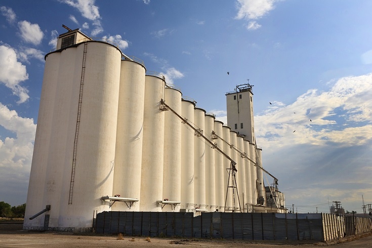
Measuring the level in silos used to hold bulk solids (Figure 1) can pose challenges. TOF devices use either the reflection based on the density of the material in ultrasonic systems, or the reflection based on the dielectric constant (DC) of the material for radar instruments. The density or DC—along with installation location, height of the silo, and the presence of disturbances such as supports, mixers, dust, condensation, and other factors—determine the best choice for each application.
Guided Wave Radar
GWR uses an approximately 1.2 GHz pulsed radar signal that travels down a guide rod (Figure 2) or cable, making it a “contact” device; that is, the rod or cable contacts the solid. The energy reflects back to the transmitter when it encounters a change in dielectric (air has a DC of 1.0 and most bulk solids are above 1.4). The transmitter divides the time down plus the return time by two, and then multiplies by the speed of light to calculate the level. The DC of the material being measured has a significant effect on the measuring range.
The lower the DC of the material, the less reflected energy, thus reducing the range of measurement. When the DC is low and the disturbances are many, or where there is heavy dust present, GWR technology can be an excellent choice. The evaluation comparison between GWR technology and radar comes down to efficiency.
As the signal is transmitted from the GWR transmitter it has a profile similar to the size of a football; that football is being guided by the rod or rope. Being guided down and back along with the smaller footprint allows for greater efficiency and less interaction with intrusions or dust. Whereas a radar signal is sent out at an angle with an increasing footprint and the reflections returning are not being guided back to the transmitter. GWR is more efficient when comparing signal transmission with installation concerns.
Ultrasonics: A Sound Choice
Ultrasonic sensors (Figure 3) use piezo crystals to generate a mechanical pulse which is launched from the sensor membrane. This sound wave reflects off the surface of the process medium due to a change in density between air and the medium. The reflected pulse is then received back at the sensor membrane. The TOF between transmission and reception of the reflected pulse (echo) corresponds directly to the distance between the sensor and the surface of the medium.
Some users moved away from ultrasonic sensors because of past problems caused by condensation. However, an ultrasonic sensor equipped with automatic self-cleaning eliminates failures caused by condensation.
By monitoring the amplitude of the signal at the sensor membrane, condensation or buildup of dust is detected by a dampening of the amplitude. The unit automatically increases frequency to the piezo crystals, creating a self-cleaning effect and ensuring the sensor membrane is free from the dampening effects caused by condensation or buildup. This feature allows ultrasonics to be used without concerns for condensation or buildup.
Ultrasonic sensors are ideal for installation in tight places due to the relatively small size of the sensor, and the option of mounting a sensor directly to the roof of a silo.
Ultrasonic sound waves need a minimum particle size greater than 0.1 inches for a reliable reflection. When additional internal level switches are necessary—such as to drive pump control—then ultrasonic may be the best choice from a lower price point.
Sound waves are attenuated by ambient temperature and moisture, so if the silo experiences large temperature variance and extreme condensation, or if steam is present, then ultrasonics might not be the best choice. Radar is not affected by temperature in the gas phase area or moisture or condensation in the air, so it can work well in these types of applications.
Pulse and FMCW Radar
Radar instruments operate within frequency bands regulated by IEEE. C-Band is between 4 and 8 GHz so most instruments operate at 6 GHz; K-Band is between 18 and 27 GHz and most instruments use 26 GHz; and W-Band is between 75 and 110 GHz, so most instruments use 80 GHz. The use of each of these frequency bands—and when and where to use them—is very specific to the wavelength and beam angle.
The smaller the frequency, the longer the wavelength. For example, we can hear a fog horn through thick fog because it produces a low frequency sound with a long wavelength to penetrate the fog. A higher frequency with a smaller wavelength cannot penetrate fog. The same is true with radar level measurements. A low frequency radar—such as 6 GHz with a longer wavelength—is better able to penetrate dust and steam than 80 GHz with its short wavelength.
Determining which frequency, wavelength and beam angle to use depends on conditions in the silo, as discussed below.
In a FMCW radar, the transmitter sends a continuous wave and constantly modulates the signal, typically from 78 to 82 GHz. The transmitter then measures the time from the sent signal (at a known frequency) to the signal returning at a different frequency. That time difference is directly proportional to the bulk solid level in a silo. Since FMCW is constantly modulating the continuous signal, adding filtering and gain settings can be much more effective in a higher frequency than if it was applied to lower frequencies, resulting in a more stable signal with accuracy of ±3mm in bulk solids.
Early FMCW radars used expensive components which consumed much more power in comparison to other TOF devices. Consequently, FMCW was only used in a four-wire instrument architecture. Over the last few years, components have been reduced in price and use less power, so it now works in two-wire systems at an affordable price. Research and field tests have proven that FMCW is best suited for the W-band or 80 GHz.
In pulse radar, the transmitter sends a microwave pulse. When the microwave energy reaches the material being measured there is a change of impendence that causes the energy to be reflected. The amount of energy reflected is dependent on the dielectric of the material being measured. As mentioned, time down and back divided by two, times the speed of light provides distance. Pulse is best suited for lower frequencies due to the resolution of the signal. Looking at the return signal in evaluation software, you’ll notice a more rounded return peak from a pulse 26 GHz unit vs a very sharp return peak in 80 GHz FMCW.
Advanced Diagnostics Improve Measurements
Advanced features such as multi-echo tracking and diagnostics have greatly improved radar level transmitters.
Multi-echo tracking identifies the different signatures of returned signals, detects false levels compared to the validated level, and ignores false signals. When the level instrument is first commissioned, a static map is generated by the operator. This can be done with an empty silo or with product in the silo. The static map then runs in the background, and multi-echo tracking processes the resulting signal. All echo signals—new and old—are mapped. If obstacles protrude into the signal path, they generate a corresponding signal and are ignored.
New diagnostics use advanced algorithms to evaluate more than 80 different problems automatically, send alarms and produce reports. For example, Endress+Hauser’s Heartbeat Technology monitors the radar transmitter for dust buildup on the horn and evaluates the return amplitude or strength of the returning signal. The returning signal becomes less and less, to the point of loss of signal over time as dust accumulates.
When the return amplitude deviates by a set percentage—10 percent for example—an alarm can be triggered long before a loss of signal would occur. This alarm could include a switch to turn on the air purge and clean the front of the horn with dust buildup. This eliminates loss of signal problems and unnecessary maintenance visits.
Another potential use of a predictive measurement could be on the electrical connections at the transmitter termination. A 24 Vdc unit may have 18 volts as a typically supply. The voltage can be monitored for either a degradation due to corrosion or a spike due to water ingress, and a “maintenance required” status can notify personnel to check the electrical termination at the transmitter before complete failure occurs.
Beam Angle & Frequency
The only significant differences between TOF and FMCW technologies is the algorithm used to calculate level. So, selecting a radar level instrument depends on the beam angle, frequency and its intended application—as opposed to picking between two similar technologies.
The beam angle—or the amount of spread in the radar signal—is dependent upon the size of the antenna and the frequency of the radar signal (Figure 5). For example, the largest spread of 23 degrees is produced by a low frequency 6 GHz radar in a 6-in. antenna. The smallest spread of only three degrees is produced by a high frequency 80 GHz radar with a 3-in. antenna.
The beam angle is important because it determines how close the radar instrument can be installed to the silo wall. The beam should never reach the silo wall because it will interfere with the radar signal, compromising both accuracy and reliability. For example, when a radar instrument with a large beam angle is installed too close to the side wall, this causes nonlinear inaccuracies throughout the measuring range.
A narrow beam angle lets the instrument be installed close to silo wall (Figure 6) and makes it easier to find a location where it will not get a reflection off obstacles in the silo, such as level switches and cross supports.
Antenna size is important because it determines the size of the opening needed in the top of the silo. Mounting an instrument close to the silo wall minimizes the need for maintenance technicians to walk on the top of the silo for servicing, thus reducing safety hazards.
Lastly, the angle of repose of bulk solids products during both filling and emptying requires an adjustment of the horn to optimize the return signals. Adjustable angle process connections allow for correct alignment to the angle of dry products in the silo.
Applications for 80 GHz FMCW instruments include silos with small process connections, as its higher frequency provides a smaller beam angle and allows for the use of smaller antenna sizes. An 80GHz instrument can even shoot through full-port ball valves or extended nozzles.
An 80 GHz radar instrument is suitable for long measuring ranges up to 410 ft, applications with many obstacles, tall slim silos, and silos with cone shaped bottoms. It also works with small grain sizes (<0.17 in.) because the shorter the wavelength, the smaller the particle size it can reflect from without a great amount of deflection away from the horn. This again appeals to the discussion of efficiency above. The more efficient the sending signal is by ensuring reflection and return to the transmitter, the more reliable the process measurement will be.
Probably the most widely used radar instrument for powder and bulk solids applications is the 26 GHz pulse radar. These instruments have been used in more than 450,000 applications involving measuring ranges up to 230 ft, extreme dust, and frequent fill and empty operations requiring fast response. 26 GHz pulse radar has less signal filtering and algorithmic processing when compared to FMCW, allowing for a faster conversion and response to process changes.
Summary
Ultrasonic and radar level instruments are the most suitable technologies for use in powder and bulk solids applications, but care must be taken when selecting the right technology, and when specifying features. One must consider particle size, beam width, and conditions within the silo, including the presence of obstacles, dust, and moisture. Working with an expert familiar with all the available measurement technologies can help simplify the task of selection and specifying the right level instrument for each application.
Dean Mallon is the national marketing manager for level products at Endress+Hauser. Previously, he was a regional level product business manager and a rep owner/partner. He serves on various industry committees, including the API 2350 4th and 5th edition working group. For more information, visit www.us.endress.com.
For related articles, news, and equipment reviews, visit our Instrumentation & Control Equipment Zone
Click here for a List of Instrumentation & Control Equipment Manufacturers
You May Also Like


