Compatibility of Scale Components
July 1, 2011
|
Accurate weighing requires a few simple steps. |
The saying “one size fits all” certainly does not apply to scales. Not only are there obvious differences in size, shape, and weighing capacity, scales also differ in the type of load cell(s) used and in the weight indicators to which they are connected. When writing the specifications for a new scale or when looking at replacement load cells or weight indicators for an existing scale, it is important to know that the load cells selected will work with the weight indicator. This article is a primer on the steps used to verify compatibility between the load cell(s), the weight indicator, and the load-receiver.
The first step is to gather the specifications on the load cell and the weight indicator. Normally these specifications are available on the manufacturer’s Web site or in the manuals received with the scale.
Let’s begin by looking at the load cell. Your scale may have one or more load cells. If your scale uses multiple load cells, they should, of course, all be of the same type and capacity. Look at the nameplate on the load cell itself or in the accompanying data sheet or on the manufacturer’s Web site and check the load cell capacity. This value is the maximum static load for which the load cell is designed and the load at which the load cell will produce its rated output. The capacity is always indicated in units of mass and is sometimes referred to as EMAX or simply capacity. The combined load cell capacity is the product of the individual load cell capacity and the number of load cells. For example, four load cells each of 1000-lb capacity yields a combined capacity of 4 x 1000 or 4000 lb.
|
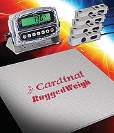
It is essential to ensure the various components of a scale work well together: load cells, scale base, and weight indicator. |
The scale capacity (the total weight of the commodity being weighed) plus the dead load (weight of the scale structure supported by the load cells) must be less than the combined load cell capacity. In our example, if the capacity of the scale is 1500 lb and the weight of the scale structure used to support the load is 300 lb, the total load on the four load cells is 1500 + 300 or 1800 lb. Since 1800 lb is significantly less than the available 4000 lb of combined load cell capacity we should be OK. Remember, however, that shock loads (dropping the commodity being weighed on the scale platform) can produce loads substantially greater than the weight of the commodity and that should be taken into consideration. In this example, let’s assume that shock loading is not a major concern. Note, too, that this assumes that the cells are equally loaded, which is seldom the case. Structures like hoppers or tanks attached to the scale often do not load the cells equally. This, too, should be considered when looking at load cell capacities. Most scale manufacturers take care to ensure that there is sufficient load cell capacity to withstand anticipated shock and off-center loading.
We’ve just considered a scale with multiple load cells but what if your scale only has a single load cell? In that case, you not only need to know the capacity of your single load cell but the scale multiple as well. The multiple is the ratio between the weight of the commodity applied to the scale platform and the corresponding force applied to the load cell. The multiple is based on the ratios of the levers making up the mechanical load-receiving structure and its analysis is beyond the scope of this basic overview. You should be able to find the multiple of your scale by looking at the scale nameplate or by checking the documentation that you received with your scale. Let’s say the load cell has a capacity of 100 lb and you have a multiple of 40. Multiplying the load cell capacity by the multiple gives you the total gross capacity of the load-receiving element, or, in this case 100 x 40 = 4000 lb. The same as what we had with four 1000-lb load cells. As before, this gross load-receiving capacity based on the product of the load cell capacity and scale multiple must be less than the sum of the load-receiving structure and the maximum weight of the commodity being weighed. Again, a 1500-lb scale capacity with a 300-lb load-receiving structure gives a total of 1800 lb, which is less than the available 4000 lb of available gross capacity.
|
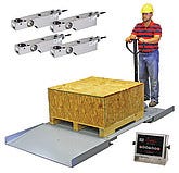
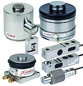
All electronic and hydraulic scales utilize one or more load cells. If the scale uses multiple load cells, they should all be the same type and capacity. |
You might think that this finishes our analysis but you would be wrong. Next, we need to make certain that the output signal from the load cell(s) is of sufficient magnitude to produce a stable weight display in the weight indicator. To do this, we need to know several things. First we need to know the rated output of the load cell(s). This is normally expressed in millivolts per volt of excitation or mV/V. Next, we need to know the excitation voltage from the weight indicator expressed in volts and the sensitivity of the weight indicator expressed in micro-volts per division (uV/d) both of which should be listed in the specifications for the weight indicator. Finally, we need to know the value of the scale division that is normally listed just below the weight display. Once this information has been gathered, the analysis can begin.
Continuing with our example, let’s assume that the load cell output is 2 mV/V. This is a common value and will most likely be what you will find yours to be although there are many load cells with other outputs so it’s best to check. Let’s say that the output or excitation voltage from your weight indicator is 10 VDC. Other common values are 12 and 15 volts but, again, check to make sure you use the right value. We find that the sensitivity of the weight indicator is 5 uV/d and that the weight indicator shows that we are using division values of 0.5 lb. The output from the load cell(s) per division must be equal to or greater than the sensitivity of the weight indicator to obtain a stable and usable weight display.
|
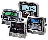
The output signal from the scale’s load cell(s) should be of sufficient magnitude to produce a stable weight display in the weight indicator. |
The output of the four cells in our example can be obtained using the following formula:
(division value) x cell output in volts/volt x excitation voltage/total cell capacity = output in volts
or
0.5 x 0.002 x 10/4 x 1000 = 0.01/4000 = 0.0000025 volt = 2.5 micro-volts per division
Since 2.5 micro-volts is greater than the weight indicator’s 2 micro-volt sensitivity, we can expect a stable weight display. Note that we converted the load cell’s rated output from mV/V to V/V by multiplying it by 1000 or simply moving the decimal point three places to the left.
What if your scale only has a single load cell? The process is the same except that we multiply the single load cell’s capacity by the scale multiple:
(division value) x cell output in volts/volt x excitation voltage/(cell capacity)x(multiple)
or
0.5 x 0.002 x 10/(100)x(40) = 0.01/4000 = 0.0000025 volt = 2.5 micro-volts per division
As before, this output is sufficient to produce a stable weight display.
If the application is non-commercial, we’re finished and know that we should have a scale that performs well. If we find a problem in the analysis, we will know that we need either a change in load cells or weight indicator or a change in the value of the weight division selected for the scale. On the other hand, if this scale is being used commercially, there are a few more steps that remain.
If the scale is used in trade, make certain that the accuracy class of the weight indicator, load cells, and load-receiving structure are correct. Unless the scale was approved as a complete device, you should be able to obtain NTEP (National Type Evaluation Program) Certificates of Conformance for the load cell, weight indicator, and load-receiver from the Web site of the National Conference on Weights and Measures at www.ncwm.net. Click on the NTEP selection and then search for an NTEP certificate.
Once found, the NTEP certificate for each component of your scale (load cell(s), weight indicator, and load-receiving structure) will include an accuracy class indication on the first page of the certificate in the FOR block. The accuracy class may also appear on the nameplates of the components and is listed as III or IIIL.
If your scale is used to weigh bulk commodities, most likely the accuracy class will be either Class III or Class IIIL. Check to make sure that the accuracy class is the same for the load cell(s), weight indicator and load-receiver. Note that Class III devices can be substituted for Class IIIL but Class IIIL devices cannot be substituted for Class III.
Next, look for a value labeled n-max. This is the maximum number of divisions the device is rated for. The load cell, weight indicator, and load-receiver may have different values of n-max but the smallest of the three must be equal to or greater than the number of scale divisions. The number of scale divisions can be determined by dividing the scale capacity by the division value. In our example, we have a 1500-lb scale capacity and 0.5-lb divisions giving us 1500/0.5 or 3000 divisions. Checking, we find that our load cells have an n-max of 5000, the weight indicator has an n-max of 10,000 and the load-receiver has an n-max of 3000. The n-max for the load-receiver is the smallest of the three values and equal to the number of scale divisions so this is acceptable. Had the n-max of the load-receiver been 2500, the scale could not be used commercially.
Finally, we need to make one more check. Listed on the load cell nameplate or accompanying data sheet is a value called the minimum load cell verification interval or V-min. This value is the smallest value into which the load cell’s measuring range can be divided. For commercial use, V-min must be equal to or less than the scale division divided by the square root of the number of cells. Let’s say that our 1000-lb load cells have a V-min value of 0.04 lb. The calculation looks like:
V-min ≤ scale division/√ number of load cells ?
0.04 lb ≤ 0.5 lb/√4
0.04 lb ≤ 0.25 lb
Because the value of V-min is indeed less than the scale division divided by the square root of the number of load cells, the scale meets the requirement.
If your scale has a single cell, the procedure is just a little different. The following formula should be used:
V-min ≤ scale division/(√number of load cells x scale multiple)
In our example, we would have:
0.004 lb ≤ 0.5 lb/(√1 x 40)
0.004 lb ≤ 0.5 lb/40
0.004 lb ≤ 0.0125 lb
Note that the V-min value of the 100-lb-capacity cell is less than the V-min of the 1000-lb-capacity cells. The application is acceptable because the V-min of the single load cell is less than the calculated value.
|
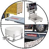
Some of the most common types of industrial scales are (from top left clockwise) floor scales, bench scales, truck scales, and tank/hopper scales. |
The procedure for verifying that a load cell or group of load cells is compatible with the weight indicator and appropriate for the application is made up of several relatively simple steps. Armed with this information, you should be able to determine if the load cell(s), weight indicator, and load-receiver are compatible and appropriate for your weighing application. More information can be obtained from the National Institute on Standards and Technology (NIST) (www.nist.gov) Handbook 44 that serves as the bible for legal metrology in the U.S. or from Measurement Canada (www.ic.gc.ca) for commercial scales in Canada.
Steve Langford is vice president of engineering services, Cardinal Scale Manufacturing Co. (Webb City, MO). He is the past president of Scale Manufacturers Association, a member of National Conference on Weights and Measures Board of Directors, member of NTEC Weighing Sector, and a registered professional engineer. He received a BS in Electrical Engineering from the University of Arkansas, a BS in Business from Missouri Southern State University, and an MBA from Missouri Southern University. Langford can be reached at [email protected].
About the Author(s)
You May Also Like

