How to Size a Dense Phase Pneumatic Conveying System
Key system sizing steps outlined using alumina powders as the sample dry bulk material to perform calculations.
November 16, 2021
Iain McNerlin and Brandon Lofquist, bulk material handling professionals, Nol-Tec Systems Inc.
Manually sizing a dense phase pneumatic conveying system is often considered a “black art” -- a type of tribal knowledge learned and passed down over time by a handful of manufacturers. In this article, we will demonstrate how to size a standard dense phase transporter system. The key system sizing steps are outlined below using alumina powders as the sample dry bulk material to perform the calculations.
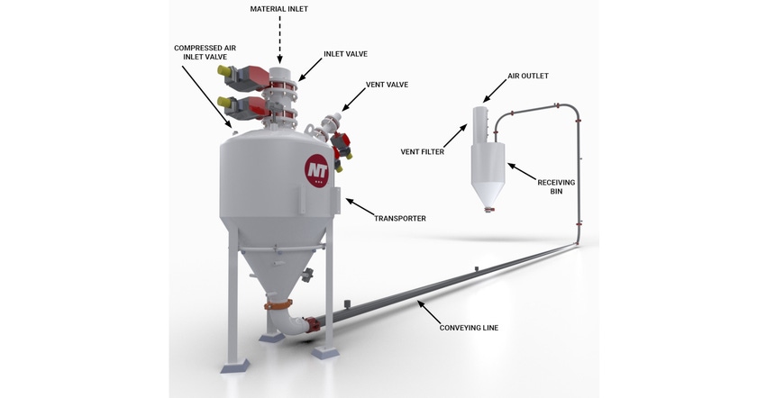
Prior to performing the calculations, a brief overview of dense phase pneumatic conveying is helpful to understand. Dense phase pneumatic conveying is a method for moving difficult, heavy (normally greater than 50-60 lb/cu ft) abrasive, mixed batch, or friable materials at a low product velocity. The system incorporates low gas volume at high pressure, conveying materials through an enclosed pipe in slug form at a controlled product velocity. Dense phase systems are favored for their reduced material segregation and degradation, minimal component wear, low operating costs, and basic maintenance needs. They are typically selected for moving material from a single collection point to either single or multiple destination points. Common materials suitable for dense phase pneumatic conveying include sand, cement, chemicals, metal hydroxides, graphene, lithium, and others.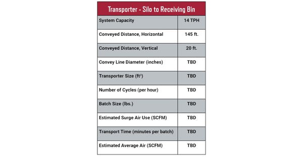
Transporter - silo to receiving bin table
System Sizing
Alumina powders are used in lithium battery production, high-purity ceramics, coatings, paints, and other specialty applications. This alumina powder has a bulk density of 70 lb/cu ft and is being transferred from a silo to a receiving bin at a rate of 14 tn/hr. The system will be a standard batch blow, purge design (purge design refers to clearing the entire line and transporter with air before refilling the transporter) needing to convey the material over 20 ft vertical plus 145 ft horizontal. In this case, a material test was conducted at our testing facility to establish the conveying rate and air usage. The test was conducted on a 165-ft line, in a 3-in. schedule 40 pipe. The test results indicated a conveying rate of 370 lb/min and an air usage of 150 SCFM.
Calculations
Step #1
Calculate the hourly volume of material to be moved.
(14 TPH x 2,000 lb/tn) ¸ 70 lb/cy cu f = 400 cu ft/hr
Step #2
Select the number of cycles per hour based on the convey distance. Alumina powder conveyed over 165 ft translates to 12 cycles/hour (the longer the convey distance, the lower the number of cycles and conversely the shorter distance the higher number of cycles; Nol-Tec uses a proprietary data set to select cycles/hr).
Step #3
Select a transporter that will use 12 cycles per hour. The hourly volume of material to be moved from step #1 is 400 cu ft/hr.
400 cu ft/hr ¸ 12 cycles/hr = 33.3 cu ft/cycle
Step #4
A 33.3 cu ft transporter is not a standard size. Therefore, select a standard size, in this case a 30 cu ft transporter and readjust the cycles per hour.
400 cu ft/hr. ¸ 30 cu ft /cycle = 13.3 cycles/hr
Step #5
Determine the instantaneous conveying rate required during an individual cycle.
60 min/hr ¸ 13.3 cycles/hr = 4.5 min/cycle. This is the total time allowed to complete one cycle. Every 4.5 minutes the transporter needs to have completed a cycle to make the system rate – note that the total cycle must include filling and conveying.
Step #6
Next select an inlet valve size and determine how much time it will take to fill the vessel. Typically, a standard 8-in. inlet valve is selected and tested to see if the system works. An inlet valve of 8 in. diameter will have a volumetric throughput of 1.25 cu ft /sec. So, the amount of time it will take to fill the transporter is:
30 cu ft/cycle ¸ 1.25 cu ft /sec = 24 sec/cycle (0.4 minutes)
Step #7
Determine how much time is left in the cycle for conveying
4.5 min (total) – 0.4 min (fill) = 4.1 minutes (to convey)
Step #8
What is the total transporter batch weight?
30 cu ft /cycle x 70 lb/ cu ft = 2,100 lb/cycle
Step #9
What is the required rate to transfer 2,100 lb in 4.1 minutes?
2,100 lb ¸ 4.1 min = 512 lb/min
Step #10
With the transfer rate established, select the proper line size that will deliver the material at a rate of at least 512 lb/min. This step references the testing results which indicated a conveying rate of 370 lb/min in a 3-in. schedule 40 line. A 3-in. line is not large enough, so the test is extrapolated into a 4-in. schedule 40 line. What rate would a 4-in. line deliver?
The rule followed here is that the instantaneous conveying rate from testing is directly proportional to the cross-sectional area of the pipe used for conveying. Meaning a known instantaneous transfer rate through a given internal diameter of conveying line at a given distance, will be the rate through any other size conveying line with the same material at the same distance resulting in a direct proportion of the cross sections of the pipes.
370 lb/min x 0.0881 (cross sectional area of 4-in. schedule 40 pipe) = 635 lb/min
0.0513 (cross sectional area 3-in. schedule 40 pipe)
Therefore, a 4-in. schedule 40 pipe at distance 165 ft will deliver the alumina powder at a conveying rate of 635 lb/min
Step #11
Next, check (at 635 lb/min), how long will it take to convey the material and confirm that it is faster than the required cycle time of 4.1 min..
So, 2,100 lb/cycle ¸ 635 lb/min = 3.30 min. Remember that the material needs to be conveyed in 4.1 min or less, so a 4-in., schedule 40 pipe will work for this application.
Step #12
Next, determine the air usage during conveying so that the compressor can be sized for the system.
Like the rule in Step #10, the instantaneous air usage during conveying is directly proportional to the cross-sectional area of the conveying pipe being used.
150 SCFM x 0.0881 (cross sectional area of 4-in. schedule 40 pipe) = 257 SCFM
0.0513 (cross sectional area 3-in. schedule 40 pipe)
During the conveying 3.30-min cycle in the 4-in. line, use air at a rate of 257 SCFM.
Step #13
How much air is used per one cycle?
257 SCFM x 3.30 min = 848 SCF
Step #14
How much air is used in one hour?
848 SCF/cycle x 13.3 cycles/hr = 11,278 cu ft /hr
Step #15
What is the “average” air use over an hour?
11,278 cu ft /hr ¸ 60 min/hr = 188 SCFM
Step #16
What is the air velocity during conveying?
257 SCFM ¸ 0.0881 sq ft (cross sectional area of 4-in. schedule 40 pipe) = 2,917 FPM
Step #17
What is the average material velocity during conveying?
30 cu ft/cycle ¸ 3.30 min/cycle = 103 FPM
0.0881 sq ft (4-in. sch. 40 cross sectional area)
By completing the above calculations, a dense phase pneumatic transport system has been properly sized. The transporter size, inlet valve, convey piping, cycle time, material velocity, batch size, and air consumption are now known values. The key to dense phase sizing--particularly with new materials--is to conduct material testing to help validate the system design. Seeing how the material conveys and then comparing those results to a set of known values makes sizing less guesswork. Nol-Tec has tested hundreds of materials and maintains an extensive database that serves as a valuable resource for our team and clients. For more information on dense or dilute phase pneumatic conveying systems or material testing, contact [email protected].
You May Also Like
