Screw Feeder Design for Metering Bulk Materials
February 20, 2018

Screw feeders are used in thousands of material handling applications and designed to meter bulk materials at a controlled feed rate. A standard screw conveyor is normally fed by another conveyor and the amount of material being discharged is directly proportional to the amount being introduced at the inlet. In contrast, the inlet of a screw feeder is always 100 percent or flood loaded and typically mounted directly to a storage device such as a hopper, bin, or silo. The amount of material discharged by a screw feeder is completely controlled by design parameters.
A hopper is typically square or rectangular in shape with sloped bottom and limited storage capacity. A bin is very similar to a hopper but with larger storage capacity. A silo is cylindrical in shape with cone or mass-flow bottom and large storage capacity.
Since the screw feeder inlet is flood loaded, the desired feed or discharge rate directly influences the design of the screw. A screw feeder’s discharge rate can be accurately determined by speed control and screw pitch design. Utilizing variable speed drives improves metering accuracy and can provide a wide range of feed rates. Pitch control is also a significant consideration in screw feeder design.
Basic Screw Feeder Design
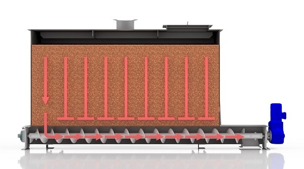
A screw is designed to move bulk materials from one flight to the next during every revolution. Therefore, if the screw is 100 percent loaded and the capacity is the same for each flight, new material can only be introduced to the first flight under the storage device, opposite the discharge. Consequently, it is not recommended to design screw feeders with uniform outside diameter and constant pitch because bulk materials will fill the screw from the rear of the inlet opening first, creating ratholing, stagnant material, and possible bridging of bulk materials above the screw feeder. Figure 1 shows the improper design of a screw feeder with uniform outside diameter and constant pitch. To draw bulk materials evenly across the full length of the inlet, each flight must increase in available volume as the screw progresses towards the discharge of the screw feeder. An effective and efficient system requires variable pitch, tapered outside diameter (OD) or mass flow screw design. Figure 2 shows a properly designed screw feeder.
Types of Screw Feeders
There are three basic types of screw feeders:
Variable or Stepped Pitch
The pitch of the screw varies from shorter to longer as the screw progresses toward the discharge of the screw feeder. With variable pitch, every pitch increases in length in the inlet section creating more available volume for the addition of bulk materials from the hopper. With stepped pitch, the flight pitch changes in increments. See Figure 3. For example, a stepped-pitch screw feeder may have 2 ft of 1/3 pitch, then 2 ft of 2/3 pitch in the inlet section.
Tapered Outside Diameter
The outside diameter of the screw is tapered from the rear of the inlet opening to the shroud creating more available volume for the addition of bulk materials from the hopper. See Figure 4.
Mass Flow
The mass flow design was developed by Jenike & Johanson and is a combination of variable pitch and tapered inside diameter. A tapered cone is located on the center pipe of the screw from the rear of the inlet opening to approximately the center of the inlet opening. Short pitch flights are mounted on the cone creating available volume for the addition of bulk materials from the hopper. Variable pitch is then added to the screw starting where the cone ends and continuing to the discharge. See Figure 5.
Screw feeders are available in a variety of sizes, lengths, configurations, and materials of construction. Most screw feeders are less than 20 ft in length because the use of internal hanger bearings is not recommended. Screw feeders can be composed of one, two, or virtually any number of screws. A screw feeder with multiple screws is considered a live bottom screw feeder. Figure 6 shows a twin-screw live bottom feeder.
A typical screw feeder is made up of the following components shown in Figure 7:
a. Screw
b. Trough
c. Discharge
d. Shroud
e. Trough ends
f. Drive unit
g. Inlet
h. Cover
Feeder Shroud
Screw feeders must be equipped with a shroud for at least two pitches beyond the inlet opening to prevent flooding of the bulk material past the inlet. The shroud is a curved cover that converts a standard U-trough into a tubular housing to prevent bulk materials from flooding past the screw. Extended shrouds, tubular housings, or short pitch flights can be utilized for accurate feed rate control when metering very free flowing bulk materials.
Screw Feeder Capacity and Speed
The pitch of the last screw flight going into the shroud determines the feed rate of the screw feeder and is called the control pitch. The control pitch is typically less than full pitch. The capacity of the control pitch is calculated in cu ft/hr per RPM. The speed of the screw feeder can be determined by dividing the maximum screw feeder capacity in cu ft/hr by the capacity of the control pitch in cu ft/hr per RPM. Most screw feeder speeds are lower than standard screw conveyor speeds. For example, in heavy industrial applications, screw feeders typically operate at speeds less than 20 RPM. More torque is generated at lower operating speeds ensuring the screw feeder does not stall at start-up.
Screw Feeder Horsepower Requirements
The horsepower and torque requirements for a screw feeder are much higher than a comparable screw conveyor. A screw feeder must start up with a flood loaded inlet and the head load weight of the bulk material in the inlet section. Bulk materials also tend to pack when under pressure in a hopper, bin or silo. As the bulk material density increases, so do the horsepower and torque requirements. The start-up horsepower and torque can easily be 2½ times the normal operating conditions. It is recommended to consult with a manufacturer that is a member of the Conveyor Equipment Manufacturer’s Association (CEMA) for proper screw feeder design.
Factors to Consider
Several factors must be considered when designing a screw feeder, including:
1. Flow characteristics of bulk material being stored and metered
2. Density of bulk material in both stored and metered condition
3. Maximum and minimum feed rate of process
4. Bulk material size with screen analysis
5. Width and length of screw feeder inlet opening
6. Overall length of screw feeder
7. Height of bulk material in hopper, bin, or silo
Other Types of Screw Feeders
Multiple Diameter Screw Feeder/Conveyor
Multiple diameter screw feeder/conveyors consist of a screw feeder with an extension conveyor. A smaller diameter screw feeder is located under a hopper, bin, or silo and is flood loaded. The screw feeder meters the bulk material to the larger diameter extension conveyor. When the bulk material reaches the extension conveyor the trough loading decreases and the bulk material is conveyed to the discharge. Hanger bearings are allowed in the extension conveyor as long as the trough loading is below 45 percent. Figure 8 shows a typical feeder/conveyor.
Live Bottom Screw Feeder
Live bottom screw feeders are designed for use on large silos, bins, and hoppers with large discharge openings. The live bottom screw feeder utilizes multiple feeder screws in tandem to create a "live bottom" to prevent bridging. Bulk materials are metered and drawn out equally from the full width and length of the inlet opening. Live bottom screw feeders are used on bulk materials which tend to pack or bridge easily. Figure 9 shows a four-screw live bottom feeder.
Inclined Screw Feeders
Inclined screw feeders meter and elevate bulk materials from hoppers, bins, or silos, and perform the same function as horizontal screw feeders. However, special care is required when designing inclined screw feeders. Figure 10 shows typical inclined screw feeders. Knowledge of the flow characteristics of bulk materials is extremely important for successful inclined screw feeder design. The angle of repose and flowability of a bulk material will determine the design of the screw feeder and the maximum angle of incline. Testing of bulk materials is required for all inclined screw feeders before a proper design can be established. Most CEMA-certified screw conveyor manufacturers have testing facilities for bulk materials and can test your bulk material before determining proper inclined screw feeder design.
Screw feeders are integral to most bulk material handling operations. Proper screw feeder design ensures successful processing of bulk materials.
Bill Mecke, P.E., is president and owner of KWS Manufacturing Company, Ltd, one of the largest screw conveyor manufacturers in the U.S. He has over 25 years of experience in bulk material handling. For more information, visit www.kwsmfg.com.
You May Also Like


