LIW Feeders: Improving Accuracy and Responsiveness
Loss-in-weight (LIW) feeders are widely used to provide reliable and consistent material delivery for a variety of challenging material handling applications.
May 27, 2020
David Hyer, president and general manager, Thayer Scale
First introduced in the 1950s, loss-in-weight (LIW) feeders are widely used to provide reliable and consistent material delivery for a variety of challenging material handling applications. Continuous innovation from several well-respected suppliers has enhanced the original design concept and expanded the range of applications that fit comfortably within the technical limitations of the technology.
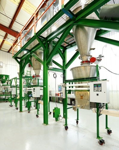
LIW feeders consist of a volumetric feeding subsystem (auger-type, vibratory, belt, or liquid discharge device), a scale subsystem, and a controller that monitors the live load information coming from the scale subsystem (see Figure 1). Various optional configurations provide material conditioning, agitation, dust-control, and communication with other plant systems. The LIW feeder is typically refilled by a much larger storage hopper that provides on-demand replenishment of material to the weigh hopper. The control unit of the LIW feeder monitors the discharge rate of the feeder and adjusts the motor of the volumetric feeding subsystem (typically using a PID control loop) to ensure the discharge rate matches the desired rate or setpoint. This rate could be a fixed discharge rate or it may be a dynamically varying rate determined by an upstream “master ingredient” or an algorithmic setpoint established by a plant DCS system. Most applications requiring a LIW feeder have critical accuracy requirements and consistent, reliable material flow must be maintained throughout the gravimetric cycle. The feeder must periodically initiate refill operations from the supply hopper and ensure consistent discharge during this time when “live” weight data is not meaningful.
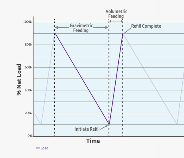
Within the gravimetric cycle (see Figure 2), the feeder discharges material under closed-loop control during the “gravimetric feeding” portion of the cycle. Once the load sensed by the scale drops to the “initiate refill” level, a refill signal is initiated by the controller, and material flows from the storage hopper into the weigh hopper. During this time, the feeder operates in volumetric control (or, in some cases, an enhanced volumetric control if a dynamic setpoint is employed). The feeder settles once the refill is complete and then resumes gravimetric material delivery.
Weighing Subsystem and the Load Cell
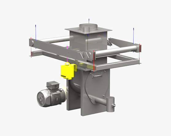
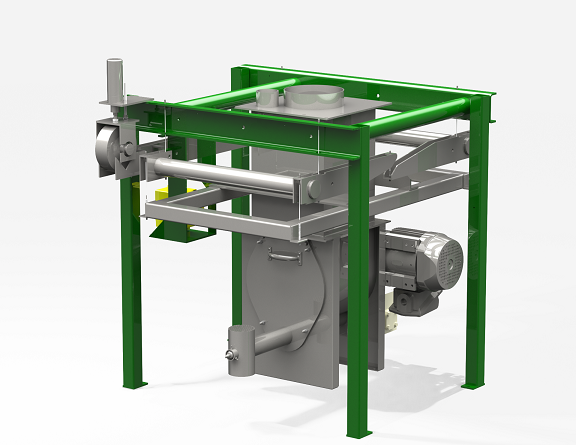
At the heart of the LIW system is the weighing subsystem (see Figure 3). The weighing subsystem typically consists of one or more load cells and mechanical features to provide accurate transfer of the vertical load to the load cells. This ensures physical isolation from undesired mechanical events such as horizontal forces, shock loads, wind, vibration, and other disturbances. The accuracy of the PID control loop depends on a highly sensitive, yet stable weight measurement from the weighing subsystem.
High-precision load cells perform the critical function of transferring the mechanical load into a repeatable electrical signal that can be processed by the controller. Today’s load cells are highly accurate, typically providing linearity better than +/-0.01% of rated capacity, and hysteresis better than +/-0.02% of rated capacity. Most load cells today provide a sensitivity of 2 to 3 mV/V excitation. Using a 15V excitation, the signal at 100% of rated capacity is 30-45mV. This signal can be amplified, digitized, and processed in a variety of ways, but the fundamental accuracy of the overall system depends on this basic building block.
Consider the example of a feeder that can hold 200 lb of material (live load). The feeder and related components (weigh hopper, motor, agitator, cover, trough, etc.) add another 350 lb of dead weight that must be carried by the load cells. Additionally, one should account for “overfill” capacity and reserve some amount of the load cell’s available range for negative weighments. The choice of the load cell is made from a finite selection of available load cell capacities (200, 300, 500 lb, etc.) once the overall load requirements are determined. As a result, it may be necessary to use a load cell (or multiple load cells) to handle 750 lb of total weight. The live-load portion of this is only 26.7% of the load cell’s total capacity. The system must also maintain a certain amount of material below the “initiate refill” point that continues to flow during refill (the heel).
Considering all of these factors, the difference between the “initiate refill” point and the “refill complete” point represents only about 20% of the load cell’s capacity (let’s call this number the gravimetric cycle load cell utilization, or GCLU). Therefore, through the entire gravimetric portion of the feeder’s operation, the analog signal provided by the load cell only varies by a maximum of 9 mV (20% of 45 mV). A typical feeder cycle may have a 5- or 10-minute gravimetric run time, which translates to a signal variation of as little as 0.015 mV/sec. If this feeder is designed to handle 10:1 turndown, the signal would be 10 times smaller when operating at the minimum flow rate or 0.0015mV. In other words, when operating at the minimum flow rate, the specified load cell error is nine times larger than the second-to-second weight variation (signal) required. It is not surprising gravimetric feeders can sometimes behave badly. Note that a standard analog strain-gauge load cell was used in this example as this has become the de-facto standard in advanced weighing systems. However, if a digital load cell or a frequency-based transducer was used, a poor signal-to-noise ratio would result. Similarly, improving controller resolution does not solve the fundamental accuracy problem created by oversized load cells.
Mass-Counterbalancing
How can this problem be addressed? One option is to stretch the time interval between samples to ensure the controller responds to real weight variation, not to noise or load cell errors. Unfortunately, this would result in a highly sluggish feeder response and preclude the use of a dynamically varying setpoint. Various other control and filtering techniques can be deployed (modifying proportional and integral terms on the PID controller, for example), but each has a similar effect of slowing down the controller’s responsiveness to an unacceptable degree. To restore the feeder’s responsiveness, we must find a way to maximize the load cell utilization (GCLU) and significantly improve the signal seen during each sample of the gravimetric operation. One way to do this is to use lightweight feeder components and attempt to minimize the dead-load, but this often results in flimsy equipment that cannot withstand the abuses of typical operating plants. These feeders may be acceptable in a lab setting, but in a typical manufacturing operation, the feeder must be designed to withstand shock loads, bumps, vibrations, and other unexpected events. The use of heavy-industry feeder components is recommended. Another option is to offload some of the feeder components (the motor, drives, etc.) from the weigh frame and attempt to couple these to the feeder using flexible electrical and mechanical connections, but this results in additional, potentially significant, sources of error. These coupling conduits present uncertain and variable forces on the scale.
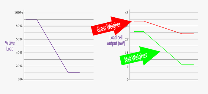
In many cases, the best option is to design a weighing subsystem that balances out the dead-load and presents to the load cell only the force directly related to the live load in the hopper. This is accomplished by incorporating a counterbalancing force into the lever arrangement of the weighing subsystem. In the example above, the mass-counterbalanced scale allows for a 250-lb load cell. This has two significant benefits. First, it increases the GCLU from ~20% to ~50%, resulting in a corresponding improvement in the signal of 2.5X (see Figure 5). Second, by using a smaller load cell, linearity and hysteresis errors are proportionally reduced. The combination of these benefits improves the controller response 2-3 times, while increasing accuracy.
Using a counterbalanced scale does have some drawbacks that need to be considered. First, with a smaller, more sensitive load cell, it is possible that overloads and shocks to the system could damage the load cell, or create a permanent shift in the load cell output. This risk can be mitigated to some extent by using mechanical stops and overload protection options. Another downside is that it creates a more complex scale design that can add time for cleaning/washdown. Special care needs to be paid to the counterweight and lever system to ensure reliable operation. Calibration may need to be performed more frequently to maintain optimal performance.
General Considerations/Conclusions
When evaluating a feeder for use in demanding applications, it is important to consider several variables that directly relate to whether to use a mass-counterbalanced scale or a gross-weighing scale. In general, there are three factors to consider:
1. Will the feeder be controlled by a dynamically varying or a constant, adjustable setpoint?
If the setpoint must vary with live conditions, such as the feeder operating as a slave in a master/slave operation, the feeder must be dynamically responsive. For this to be possible, the controller needs frequent, reliable load data. Without a large signal-to-noise ratio, this may not be possible.
2. What is the targeted gravimetric run time? And how consistent/reliable is the refill operation?
If it is necessary to support a long gravimetric run time, either due to the type of refill operation available, or to support a high turndown, it is important to maximize the GCLU. On the other hand, if the refill system can support short, frequent, consistent refills, a gross-weight feeder can be sized to maximize the load variation per unit time, and operate quite successfully in this environment.
3. What is the overall accuracy requirement for the system?
If the process requires a consistent material delivery of better than 0.5% variation in a 30-second material delivery window, the high sensitivity and superior accuracy of a mass-counterbalanced scale are likely warranted. However, a gross-weighing system is sufficient for batch operations or metering material with lower precision requirements.
Running material in a material test center that permits you to run both is often the best way to determine whether a gross-weighing solution or a mass-counterbalanced feeder is the best option. Most suppliers offer comparison testing of multiple feeding options.
David Hyer is president and general manager, Thayer Scale. For more information about Thayer Scale’s material test center or to schedule a test, visit www.thayerscale.com/thayer-material-test-center.
You May Also Like


