Gravimetric Feeders: The Achilles' Heel of Continuous Manufacturing
February 13, 2018

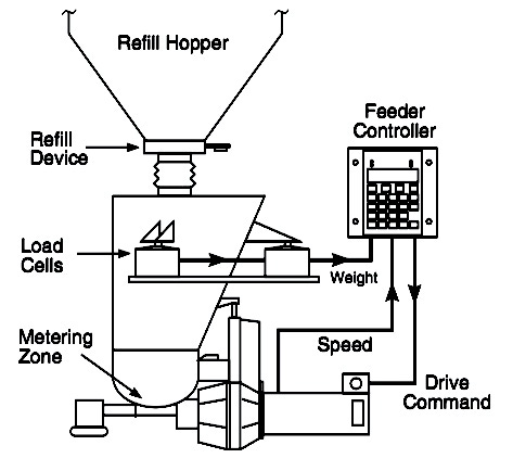
Gravimetric feeders are frequently used in continuous manufacturing processes. A gravimetric feeder relies on a control system that adjusts the speed of the feeder based on loss-in-weight measurements. Since the controller is unable to discern the discharge rate when its hopper is being filled with new material, two hoppers arranged in series are typically used. The lower hopper is frequently asymmetric with at least one steeply sloped wall to reduce the likelihood of flow obstructions. Such geometries often result in a highly variable solids velocity distribution, which can exacerbate segregation. In some hoppers, an agitator is used to ensure that it has a "live bottom" and no dead zones. During the fill cycle, the downstream feeder is operated in a volumetric mode (i.e., at a constant speed). The feeder then operates in gravimetric mode (i.e., its speed is controlled by measuring the loss in weight of material inside the hopper) after the downstream hopper has been filled. A schematic of a gravimetric feeder is given in Figure 1.
Most powders are compressible. The bulk density of a powder increases with increasing consolidation stress, varying rapidly at low stresses and less dramatically at high stresses. A typical compressibility curve is shown in Figure 2, where the bulk density is plotted against major principle stress. The major principle stress is the stress that would be measured on a plane that gives the stress its maximum value.
Because of the hopper's odd geometry, the powder will remain in what is called an active state of stress. When in an active state, the direction of maximum stress is downward. If an additional stress were applied to the powder, for example, if a slug of powder were dropped from the upper hopper into the lower hopper, the stress would be transmitted vertically toward the powder and, being compressible, its bulk density would increase. The feeder would be unable to compensate for the change in bulk density because it was in volumetric mode during the fill cycle. Because the bulk density of the powder had increased during filling, the discharge rate during the fill cycle and the begging of the emptying cycle can be higher than before. This is illustrated in Figure 3, where the discharge rate is calculated by measuring the gain in weight in a container filled by the feeder.
When the lower hopper is emptying and the feeder is operating in gravimetric mode, the discharge rate is very steady. The bulk density of the powder is not necessarily constant, but the control system compensates by reducing the feeder speed if the density increases and vice versa. Unfortunately, during the fill cycle, the impact of fresh material compresses the powder in the heel of the contents of the hopper. This means as the bulk density increases, the controller does not adjust the speed due to being in volumetric mode.
There are methods to dampen the variability. For example, fresh powder can be added more frequently so that less of a load will be imparted during the fill cycle and the time the feeder must remain in volumetric mode is shortened. Also, modern controllers are more predictive: they can estimate the higher bulk density that accompanies the fill step, which provides an estimate of the feeder speed required when the feeder returns to gravimetric mode.
Variability can also be reduced by modifying the converging section of the lower hopper for mass flow. Mass flow occurs when the hopper walls are steep enough and low enough in friction to ensure flow along them. With mass flow, a passive state of stress will develop when the powder is discharged from the bin, and this passive state of stress will remain during refill. The powder is compressed laterally and expands vertically, and as a result, the major principal stresses act horizontally instead of vertically. A typical major principle stress profile is shown in Figure 4.
Figure 5 shows the solids stress profile at the end of the emptying cycle and the start and end of the fill cycle. At the start of the refill step, an additional load is applied to the powder as a result of impact of the new material. Because the lower hopper is a mass flow hopper, a passive state of stress exists. As a result, the solids stress at the hopper outlet is nearly constant. Consequently, the bulk density of the powder, which is related to major principle stress by its compressibility curve, also does not change.
Figure 6 shows the discharge rate of powder from the lower hopper designed or modified for mass flow. Note that there is no significant change in the discharge rate when the feeder operates in volumetric mode.
Continuous manufacturing requires steady feeds. The likelihood of having a reliable gravimetric feeder is greatly improved if its lower hopper is designed for mass flow. Wall friction testing is required to determine the recommended mass flow hopper angle.
Greg Mehos, Ph.D., P.E., University of Rhode Island and Stephanie McClory, University of New Haven. For more information, visit www.mehos.net
For related articles, news, and equipment reviews, visit our Feeders Equipment Zone
Click here for a List of Feeder Manufacturers
You May Also Like


