


Sign up for the Powder & Bulk Solids Weekly newsletter.
Spray Dryer Optimization
17 Min Read
.svg?width=850&auto=webp&quality=95&format=jpg&disable=upscale "Spray Dryer Optimization")
|
A large dairy multistage dryer with insulation panels that can provide substantial energy savings |
The question is often asked, “How can more capacity be gotten from our spray dryer?” Or, “What is the greatest amount of powder that this dryer can produce?” Optimization of a spray dryer most often means greater capacity, greater energy efficiency, and lower manpower input.
Optimization is a complex and multifaceted goal that is best looked at in three ways. First, one can address the question from the standpoint of maximizing any single hour of production—that is, by maximizing inlet temperature, outlet temperature, feed temperature, feed solids, etc. This procedure can be both theoretical and scientific.
The second way to address the problem is on a monthly basis. In a 30-day month, there are 720 hours during which a dryer can run. How many hours per month is it in fact running? How many hours per month are lost to clean in place (CIP)? How many hours are lost to process-related problems such a plugging, build-up, etc.? In many cases, more production can be achieved by reducing downtime than by trying to operate each production hour close to the theoretical maximum.
The third, and often overlooked, approach is to maximize dryer production on an annual basis based on changes in ambient conditions. Spray dryers almost always run better in winter than in summer. This has to do with the amount of moisture in the ambient air. When the moisture in the ambient air is higher, less water can be evaporated in the spray-drying process.
Because each optimization procedure has unique requirements, it is difficult to give one-size-fits-all answers. But if an operation is analyzed critically, if the right questions are asked and if clear methods are applied to find solutions, operations can be improved.
Improving Capacity
Simply stated, the capacity of spray drying is measured by the amount of water evaporated. Evaporation is defined as the difference between inlet and outlet temperature, or ΔT, in the drying air. The larger the ΔT, the greater the capacity of the spray dryer. The goal in optimizing a spray dryer’s capacity is to increase ΔT by raising the inlet temperature or lowering the outlet temperature.
What is the optimal outlet temperature? The outlet temperature is a manifestation of the relative humidity in the outlet air. If the outlet temperature is too low, the product particles in the drying chamber will not become dry enough in the time allowed, enabling sticky particles to cause blocking or plugging. If the outlet temperature is too high, excess capacity remains unutilized. The proper outlet temperature—or more specifically, proper outlet relative humidity—is product- and dryer-specific, but once established, it remains constant for a specific product in a particular dryer.
To develop a viable dry particle, a dryer should operate just on the safe side of “dry enough” while avoiding “too dry,” which results in underutilization. Understanding these principles and using a modern control system with the instrumentation needed to collect operating data are the primary means to achieve optimal drying conditions.
An instrument for measuring incoming air moisture is key to good operation. Using instrumentation to determine when the ambient conditions change allows operators to adjust the drying parameters to account for changing conditions while maintaining optimized production.
|
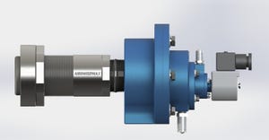
The Niro CIP nozzle valve features a retractable design. |
Another key to achieving optimal drying conditions is spray-dryer inlet temperature. The higher the inlet temperature, the more energy is available for evaporating water. Obviously, spray dryers do not operate with infinitely high inlet temperatures. There are good reasons for limiting inlet temperature, and they are generally process, product, or safety related. Inlet temperature can be limited for process reasons when the ΔT has been optimized and the maximum outlet humidity has been reached. This means evaporating as much water as possible and operating just above the product’s sticky point.
Build-up can occur in vessels that operate above a certain inlet temperature or below a certain outlet temperature. In addition, vessels can experience bridging. This is a manifestation of operating with a ΔT greater than that which can produce a viable dry particle.
Inlet temperature can also be limited for product reasons. If the product becomes denatured, burned, deprived of desired volatiles, or degraded in other ways at high inlet temperatures, the drying inlet temperature is limited to a point below which the undesired characteristics do not occur.
Another reason for limiting the inlet temperature is related to safety. If product builds up in the dryer, particularly in areas next to high-temperature surfaces, product may ignite. Sugar-based products can autoignite when wall build-up reaches certain thicknesses at certain moisture levels and temperatures. Being aware of these conditions enables users to set reasonable limits for the inlet temperature.
Plant operators should know why inlet and outlet temperatures are set at particular levels. Just because limits exist and the spray dryer has run for years does not mean that operating conditions should not be evaluated and optimized. Limits are often in force for reasons that no longer exist.
Feed temperature, particularly in existing plants, can also be optimized. Theoretically, heating feed as close to the dryer’s inlet temperature as possible is ideal. All of the energy available from the air heater can then be used for water evaporation, with no energy going toward heating the residual product. In most cases, it is not possible to heat the product greatly without causing product degradation. Elevating the temperature as high as the product allows without degradation yields extra capacity from the spray dryer by acquiring heat from a source other than the main air heater.
Finally, using the highest concentrations of feed solids yields greater capacity. This topic, however, is beyond the scope of the spray dryer itself.
Decreasing Downtime, Increasing Run Time
A plant may decide at some point that it requires all of the 720 hours in a 30-day month to meet its production requirements. During a production month, there are two ways to understand the amount of time that is not spent in spray drying. The first is the planned time spent performing processes such as cleaning or CIP. The second is dryer-related unplanned downtime, such as unplugging cyclones. Even if a plant does not need all 720 hours, operating in the most efficient way possible leads to labor savings.
If the dryer feed system is down for cleaning, dryer downtime results, reducing the amount of available time in a production month. In a food or dairy plant, the feed system for the spray dryer often must be washed or CIPed daily. In food plants that often switch between products, batches and products must be separated. A hot issue is dealing with allergens and cleaning between allergen classes.
Many simple incremental operational improvements can be made in the feed-system CIP to shorten turnaround times. For example, is the labor required to remove nozzle lances from the spray dryer and hook them up for cleaning proceeding as efficiently as possible? A second set of nozzle lances that has been pressure tested and is ready for installation will save operators from having to cover the same ground twice.
There has been a trend toward using spray dryers with two feed systems, each of which can operate at 100% capacity. While this procedure works particularly well for nozzle atomization systems, it can provide benefits for rotary atomization systems as well. If feed-system CIP requires that a spray dryer be down for several hours per day or week, those hours can be regained by using a dual-feed system.
A dual-feed system can be used in two ways. First, and most simply, an exact duplicate of the feed system, whether rotary or nozzle, can be built up to the point of connection with the atomizer. When feed system 1 is shut down at the end of a batch, the nozzle lances or rotary atomizer are removed for cleaning. Clean nozzle lances or a clean rotary atomizer are immediately installed and connected to feed system 2, after which the spray dryer is put back into operation. Then feed system 1 can be cleaned when convenient. In this procedure, CIP does not interfere with production.
|
A service technician with a spray dryer |
Generally, switching between two feed systems can take between 30 and 60 minutes. But the 1 to 3 hours required for CIP do not cut into production and are gained back as time available for spray drying.
The second way to implement a dual-feed system is more complex and only applies to nozzle atomization. This method requires an air disperser with double the number of nozzle lance locations. If a dryer has 6 nozzles, the air disperser must be rebuilt to hold 12 nozzles, 6 of which are used at any given time. Then the spray dryer will never have to be shut down. At the end of a batch, the processing speed of feed system 1 is reduced while the processing speed of feed system 2 is ramped up. Production capacity always remains constant during this operation. Feed-system CIP setup is taken out of the critical path and can be performed when convenient.
If CIP is not planned immediately after the feed-system switch, accommodations can be made for the high-pressure feed system to purge the nozzle lances with compressed air, or a recirculating loop can be created to flush the system with water. An added benefit of using a dual-feed system and switching back and forth is the reduction of drying-chamber fouling, which is most often caused by startups and shutdowns. If startups and shutdowns can be minimized or eliminated, the time between chamber washes can be extended. With fewer startups and shutdowns, the use of fans and heaters between spray-drying operations can be reduced, resulting in energy savings.
Spray-Dryer Cleaning
Aside from operations, the most important events in the life of a spray dryer are planned or unplanned cleans. For some operations, cleaning may be performed daily to separate batches or allergen classes. For other operations, cleaning may take place annually.
First, personnel must ask why the spray dryer is going to be cleaned. Generally, there are five answers to this question:
1. To remove buildup that can result in fire or explosion.
2. To eliminate buildup that is causing product quality issues.
3. To separate product groups or classes to prevent cross-contamination.
4. To eliminate bacterial growth that can cause product quality issues.
5. As part of regularly scheduled maintenance.
Often, cleaning is performed to address and eliminate the root causes of production issues. If buildup can be minimized—for example, by performing fewer startups and shutdowns—wash frequency required for preventing fire hazards or product quality issues can be reduced. Ultimately, maximizing the time between cleans or CIPs will also maximize the time allowed for production.
While performing cleans, three areas can be evaluated to achieve the most efficient time utilization: setting up the dryer for cleaning or CIP, the cleaning or CIP procedure, and drying out the equipment and preparing it for production again.
Setting up a CIP and preparing equipment for production are generally manpower issues. Establishing piping connections or isolating pieces of equipment can be accomplished using more manpower or automation. For example, if spray balls are still being installed manually, permanently mounted retractable spray balls can be added to reduce labor and time requirements.
During the cleaning or CIP cycle itself, timelines can be improved by addressing the four parameters that affect cleaning: solution delivery pressure, solution chemical strength, solution temperature, and duration. Improving any of the first three parameters generally reduces the time required to complete a cleaning cycle. With one or two operators, performing a simple hot-water clean of a small-sized modern spray dryer system to separate product types or batches can often be accomplished in approximately three hours—from going off-line to resuming production. Chemical cleans of a larger dryer with a month’s worth of production build-up can be turned around in 8–16 hours. In many operations, however, 24–48-hour cleans are highly valued.
|
The integrated filter dryer features an integrated fluid bed and filter arrangement. |
Unplanned Downtime
In dealing with unplanned downtime, there are myriad mechanical- and process-related reasons for shutdowns. One of the most common causes of unplanned spray-dryer downtime is the plugging of cyclones, chamber outlets, conveying lines, and similar equipment. Plugging has two main causes: mechanical issues and moisture. Mechanical issues—whether bridging or reduced flow—are much easier to deal with than moisture. These problems are handled using mechanical means such as pneumatic hammers, bridge breakers, or increased outlet sizes.
The more difficult issues include moisture and condensation. By definition, the air inside a spray-drying process vessel—be it a chamber, cyclone, or baghouse—is moist and warm, while the temperature outside the vessel is cooler. If the internal surface of the vessel is allowed to cool below the dew point of the moist air, condensation will occur. For a process with a 160°–180°F dryer outlet temperature, dew points can be in the range of 120°–130°F. If the room in which the vessel is situated is 80°F, there is enough temperature differential to cause heat loss and condensation, leading to product plugging or bridging. If the vessel is insulated and clad or heat jacketed, these problems are generally eliminated. Nevertheless, other conditions exacerbate the problems.
A crucial component is the cyclone tip or product outlet. In the cyclone tip, the rotational velocity of the air is high. Inversely, because the air velocity is high, the air pressure is low. For example, in a high-efficiency cyclone with 6 in. of water column differential pressure between the air inlet and outlet, the static pressure in the tip can be –20 in. water column. Such low pressure would be the same as moving the plant from sea level to 1400 ft above sea level. Such low absolute pressure in the area of the cyclone tip causes fog or condensation in the air.
Why is the cyclone tip the most problem-prone component of a dryer? If three effects are combined—smeared product caused by rotation, air leakage into the cyclone from a rotary valve or similar device, and the low absolute pressure inside the vessel—plugging can occur.
A second area to explore is the nozzle lances in a nozzle spray dryer. Operators regularly install and remove nozzles, disassembling and reassembling them. Handling the small parts that comprise a spray nozzle and assembling them correctly so that they can operate at many thousands of pounds per square inch of pressure is difficult. Incorrectly installed spray nozzles result in poor product quality and require operators to shut down and restart the spray dryer, leading to production losses.
One way to solve this problem is to pressure test the nozzles before they are installed. A small operation can be set up either near the dryer top or in another part of the plant in which a small industrial high-pressure pump is used to test each nozzle with water after it has been assembled. This test can be done on a second set of nozzle lances while the dryer is operating so that the tested lances can be installed during the next changeover.
Effect of Ambient Conditions
Humidity levels in the dryer inlet air resulting from the seasonal variability in ambient air conditions play an important role in standardizing incoming air in open-cycle dryers and dryers without inlet-air cooling systems. To understand this, it is necessary to understand a primary maxim of spray drying: Dryer capacity is limited by the total moisture in the air leaving the spray-drying chamber. In simpler terms, if the air leaving the chamber is too moist, a viable stable particle is not produced and the product tends to be sticky. If the air leaving the chamber is too dry, some drying capacity remains unused. To maximize dryer capacity, the dryer should be operated as close as possible to the maximum total moisture of the chamber outlet air, a parameter measured in pounds of water per pound of dry air (lb lb).
Once the dryer inlet temperature, dryer outlet temperature, and other parameters have been optimized for a specific product under specific conditions, dryer outlet moisture will be optimized. Then the plant should be operated as close to this theoretical maximum as possible. This procedure is difficult to carry out because of weather and seasonal changes.
Facilities often hope to solve this difficulty by installing an instrument to measure the total moisture of the chamber outlet air and then program a control loop to allow the dryer to operate at a setpoint just below the maximum. This is not possible, however, since any commercially available instrument, such as a hot-wire anemometer or a humidity transmitter, would be quickly fouled by the powder in the air stream. The problem must be approached from a different angle.
First, it is important to understand the three sources of water in the outlet: the humidity in the ambient air absorbed into the dryer, combustion products if a direct-fired gas burner is used as a source of heat, and the water evaporated in the spray-drying process. If the moisture contributions from the first two sources are reduced, the contribution from the third can be increased. If the moisture from the first two sources can be measured and controlled, one can operate with much less of a margin on the third and thereby maximize capacity.
How does one measure and control this? Using the units of measure used for outlet humidity (lb lb), every contributing component is measured. This means measuring the two or three components that contribute to the water total and all of the air components.
First, it is necessary to measure the ambient air moisture with some sort of hygrometer that sends data back to the control system. If some air is taken from inside the plant and some from outside, two instruments can be needed. Air volume must be measured for each air stream. This can generally be done using a pitot tube with a differential-pressure transmitter, which calculates the air volume in the control system. Alternatively, something similar can be done using a hot-wire anemometer.
If a spray dryer has a direct-fired gas burner that runs on natural gas or propane, moisture is added to the drying air stream as a product of combustion. This can amount to a 5 to 10% increase in the moisture contribution, depending on the specific conditions. An accurate gas meter can send the gas consumption data to the control system, where a stoichiometric calculation can be made to calculate the exact moisture contribution.
Finally, the volume of water contribution from the evaporated water must be measured. Since either a nozzle spray system or a rotary atomizer system is fed with a positive-displacement pump, the volume of water pumped into the dryer can be calculated from the pump speed, pump displacement, and solids content. This procedure is generally more accurate than using a flowmeter, but mechanical inefficiency and slippage must be accounted for to ensure accuracy.
When all the moisture and air inputs have been collected, the final calculation can be made in the control system. Operational data must be collected to indicate when the dryer is operating correctly and when it becomes plugged. Alarms or automation systems can be put in place to ensure that the spray dryer is operating at its optimum level without being in danger of plugging or experiencing a wetdown condition.
Conclusion
Corporate profitability drives the need to understand the science of spray dryers and their optimization. Consequently, the cost of implementing any of the suggestions discussed in this article must be weighed against the opportunity cost of an extra pound of production or an extra available hour of uptime. No move in the direction of optimization can be justified unless it results in a positive financial outcome.
Jim Kent is the sales manager for the food and dairy division of Niro Inc. in Hudson, WI. Kent has a BS in aerospace engineering from the University of Minnesota. He can be reached at 715-377-0536 or [email protected]. John McLeod is the rebuild sales engineer of Niro Inc. in Columbia, MD. McLeod has a BS in chemical engineering from North Carolina State University and an MBA from the University of South Carolina. He can be reached at 410-997-6670 or [email protected].
About the Author(s)
You May Also Like
Editor's Choice


.svg?width=800&auto=webp&quality=80&disable=upscale)