


Sign up for the Powder & Bulk Solids Weekly newsletter.
Design Considerations for Pneumatically Conveying Coal
Pat Mahoney
January 11, 2007
7 Min Read
.svg?width=850&auto=webp&quality=95&format=jpg&disable=upscale "Design Considerations for Pneumatically Conveying Coal")
|
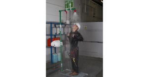
The cartridge element can be removed without maintenance |
If you asked six different engineers to develop a pneumatic conveying system, you would likely get at least six different designs. This article contains a series of reflections on some of the concepts that were applied in an actual installation and the reasoning behind the different approaches. The overview includes helpful hints and insights into the decision-making processes concerning convey-line construction, filtration, storage, and temperature as they affect a dilute-phase conveying system. Although this article focuses on coal conveying, the principles discussed here can be applied to many other materials.
The journey begins with a coal processor that incorporated a dilute-phase pneumatic conveying system into production. The processor delivers a wide variety of coal types via railcar. The coal is then crushed and dried before being introduced into the pneumatic conveying system at ambient temperatures. Then the material is stored, processed, and pneumatically conveyed once again, but at elevated temperatures. The final product is formed into billets.
Convey-Line Construction
The components of any pneumatic conveying system must work in concert. At the heart of the system is a design that relies on proper pick-up velocity and an accurate prediction of pressure drop. In the case discussed here, a minimum pick-up velocity was determined during lab testing. Material velocity must be used in the right context. Sometimes, programming velocity and the convey-line routing of cohesive and adhesive materials in a typical pressure-drop algorithm can produce erroneous results. Coal, although dried, still has sticky properties. Also, a wide variety of coals can be processed. Utilizing a material-to-air ratio that was often 8:1-and sometimes less than 10:1-limited the particle-to-particle interaction and made pressure-drop prediction accurate. This approach made the calculations for blower size and horsepower selection rudimentary with confidence.
The convey line was specified as carbon steel by the customer. The selected wall thickness was Schedule 10 pipe. Since crushed coal demonstrates mildly abrasive properties before being processed, the convey line started to show signs of wear after about three years. In particular, the elbows for certain grades of coal had to be replaced. The replacement elbows consist of a channel that is rolled the hard way and welded to the back. Should a hole wear through the primary elbow, material fills the void created by the channel. Eventually, the fill material will match the point at which the conveyed material abrades against itself. Successful so far, this approach was employed primarily because of the high initial capital cost of custom abrasion-designed elbows. It was easy to fabricate in-house. The convey line is coupled with four-bolt compression couplings, and leaking at the joints has not been an issue. The coupling should be tightened, retightened, and then anchored to the support. If the piping is anchored first, the interior metal sleeve can fold, making it difficult for the coupling to seal.
The Filtration Challenge
The filtration on the top of the silos posed an interesting challenge. A filter assembly was needed that would not require maintenance personnel to enter an enclosed housing to change out the filter bags, since the material is extremely fine and dusty. Multiple single-cartridge filter assemblies are used on a single silo. The filter assemblies each have a dedicated compressed-air and pulse-clean arrangement. The top section of the assembly can be removed using a toolless clamp, simplifying filter extraction. The single element can be pulled upward out of the housing, placed into a bag, and lowered to the bottom of the silo. As a result, personnel experience minimal exposure to dust.
The filter media and pulse-clean assembly required a more in-depth review. The initial consideration was an air-to-cloth ratio of 1:1, with open-pleat spacing for the cartridge element. This approach was relatively conservative, but it was necessary because the particular type of coal dust in the facility does not release easily during cleaning. The design had to be further enhanced and rendered more efficient. Two components contributed to the final arrangement: the filter media and the pulse-cleaning device. The filter media were a 100% spun-bond polyester cartridge with a PTFE exterior membrane. These media solved the problem of releasing the material from the filter. However, because the material has the natural tendency to cling to the surface, a review of the pulse-cleaning design was required.
Premier Pneumatics Inc. wanted to improve both the reverse airflow that is used to clean the filter and the physical shaking of the element. The company considered two equally important modifications: increasing the volume of the compressed-air accumulator and the line size feeding the accumulator. While the larger accumulator provides a more pronounced in-rush of air during the initial cleaning stages, the larger line size feeding the accumulator improves overall air flushing into the filter for the duration of the cleaning process. These modifications improved overall filter performance appreciably.
Added Benefits
The use of several individual filter assemblies at the top of the silo has other benefits. The filter elements generally hang below the deck of the silo, eliminating concerns about can velocity (the average upward air velocity in the filter housing). Because the filter element can drop into the open space of the silo, the element is subjected to limited dust recycling. In addition, the modified system does not require a fan. Traditionally, a fan was included with the filter used on a silo. The fan balanced out the pressure drop of the filter assembly. It also aided purging at the conclusion of a PD truck’s filling cycle, so that the pressure relief valve on the silo would not open. However, the modified system does not incorporate a fan, and the pressure relief valve on the silo stays closed during all phases of the fill cycle. While proper filter-media cleaning is the main reason a fan is unnecessary, the presence of multiple exhaust paths also helps to control airflow surges. These design modifications have resulted in increased efficiency, improving the air-to-cloth ratio to 4:1.
The modified system uses round silos that are 12 ft in diameter by 60 ft tall. Each silo incorporates a bin activator that exceeds the rule-of-thumb size-half the size of the diameter. The silos also incorporate leg supports. This type of support results in a tighter fit for mounting the larger bin activator size. Particular attention was paid to the cross-bracing, especially around the bin activator motor. All of these modifications have resulted in a much tighter layout than the original configuration.
Level Indication
Another component of the storage package is level indication. While capacitive-type level indicators have been used successfully with coal, different types of coal and the extent to which they are dried lead to changes in dielectric constant. Consequently, calibration is difficult to maintain. Ultimately a simple yo-yo-style level indicator was employed. Activated by a timer, it indicates whether the material being stored is in a static state, being filled, or draining. It is usually recommended that a yo-yo-style indicator be deployed while the material is in a static state. In this case, plant personnel have used it in this manner without incident.
The Importance of Temperature
Crushed coal undergoes a series of processes that raise its temperature to 250°F. At that temperature, the material is more abrasive than in its original form. An airlock feeds the material into the pressure system. The machine clearances must be opened between the rotor and the housing. If not accounted for, the temperature rise will cause the rotor to expand and lock up. If there is too much clearance, air leakage can prevent material from feeding properly. A wear alloy metal can be used for the rotor to alleviate wear issues. A tungsten-carbide thermal spray treatment can be used to achieve even longer life. The high temperature affects not only the airlock, but also the filter. The filter cartridge has been modified so that an end cap has been welded to the internal support and then mechanically fastened to the bottom pan. High-temperature potting is used to seal the bottom pan to the media. If the material should exceed 275°F, the bottom pan will not fall off. However, such heat exceeds the temperature specification of the potting and media.
Several aspects of the pneumatic conveying system modification discussed in this article have not been presented. Hopefully the article will encourage users of such systems to develop their own ideas for applying the technology to meet their manufacturing needs.
Pat Mahoney is senior systems engineer supervisor at Premier Pneumatics Inc. in Salina, KS, a manufacturer of pneumatic conveying systems and components. He can be reached at 785-825-1611 or [email protected].
About the Author(s)
You May Also Like
Editor's Choice


.svg?width=800&auto=webp&quality=80&disable=upscale)