Scale Techniques: Which Method Is Right for You?
July 6, 2007
To achieve optimum performance of an electronic weighing system, accurate calibration of the system and correct selection of the load sensors, mounting hardware, and other installation assemblies are essential. During installation, the accuracy of the system may be affected by external factors such as restraints caused by the addition of process piping, surrounding equipment such as motors and valves, or any deformation of the supporting structure. Field calibration at the completion of installation, followed by verification of the calibration at periodic intervals thereafter, is recommended. There are many acceptable ways to calibrate a scale, all of which depend on the degree of accuracy required.
Using one calibration technique rather than another will depend on the accuracy you want to achieve, and the time you want to spend on the process. This article describes all calibration techniques in detail, so you can decide which method is best for you:
• Hardware calibration using certified weights.
• Hardware calibration using material substitution.
• Hardware calibration using test weights with material build.
• Alternate calibration techniques.
|
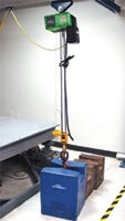
Scale calibration using certified weights |
Hardware Calibration Using Certified Weights—the Most Accurate
This method uses known calibrated weights to apply a load onto the load-receiving elements. Because the traceability of the standard is known and maintained, it is the most accurate calibration technique. Accuracies within 0.05% of the applied load can be achieved with this method. However, this procedure may be restrictive for some industrial scales, as large-capacity weights are not easily transferred to the site or often unavailable in the field. In many other cases, the load-receiving element may not be able to accept placement of the weights, or is in a poorly or inaccessible location, such as a vessel hanging high above the factory floor.
To use the certified weights method of calibration, a set of Class F accuracy weights (within 0.01% of denomination) that meet the following regulations are required:
• A total weight of 80 to 100% of the system capacity.
• At least three weights between 10 and 100% of the system capacity to check the midrange.
• Several low-capacity weights, equivalent to one or two instrument divisions.
Most local Weights and Measures organizations have such weights available. Typical weight values are 10, 25, 50, 100, 500, and 1000 lb. If the weighbridge is a device other than a platform, some method of loading the weights on the structure must be devised.
Hardware Calibration Using Certified Weights: Step-by-Step Procedure:
1. Turn the scale on and allow it to warm up for one hour so the system can stabilize to its ambient temperature. Check that the scale operates properly and within specifications.
2. Load and unload the scale to its maximum load several times to check repeatability. On a new installation, this process seats the load points and checks for possible mechanical restrictions from incorrectly installed checking or piping arrangements.
3. With no load applied to the scale, zero out the instrument’s display.
4. Apply the certified weights to the scale, from 80 to 100% of its full capacity, in ascending order to reduce any difference in up-scale and down-scale readings.
5. Set the displayed weight (span) of the instrument to show the certified value of the weights applied to the scale.
6. Remove the certified weight load and allow one minute for the instrument display to read zero. If zero has changed, repeat the previous steps until the display accurately shows both zero and the applied load.
7. Starting from a zero load, apply partial loads (e.g. 25%) to record any deviations in the scale's mid-range.
8. Apply a low-capacity certified weight to check the system’s sensitivity and possible mechanical restrictions. Apply it at the zero, midrange, and maximum load points.
9. Record the deviation as the weight is applied and removed. A poor return shows low sensitivity or mechanical restrictions. Correct this problem before proceeding.
10. Verify the scale by making at least three runs after the scale has been checked.
11. Refer to your state or local authority for regulations concerning calibration of scales used for commercial weighing. Also refer to the National Institute of Standards and Technology (NIST) Handbook 44.
Hardware Calibration Using Material Substitution
|
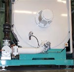
Scale calibration using material substitution |
When certified test weights are not available, accurately weighed material may be used to calibrate a system. In this method, material weighed on a secondary, calibrated scale is delivered to the site of the scale to be calibrated. The secondary calibrated scale should be of the same accuracy or greater, and have an approximately equal capacity. Material introduced is dependent on what the vessel is designed for. The methods used for delivering the material for calibration must not be overlooked since they may lose or gain weight during transit. (For example, if a truck is part of the delivered weight, it loses fuel during the transfer.) Snow, rain, or other environmental characteristics might alter the precision of the weights. Accuracies of up to 0.15% of applied load can be achieved.
“Warm Body Calibration,” a common method of material substitution, is easy but it yields a much lower accuracy. Multiple workers get weighted on a secondary scale, then they climb onto the scale (vessel) being calibrated. Extreme care must be taken to ensure that no injuries to personnel or damage to equipment occur.
Hardware Calibration Using Material Substitution: Step-by-Step Procedure:
1. Follow steps 1–3 of Hardware Calibration Using Certified Weights.
2. Fill a container (drum, box, truck) with the material to be used.
3. Weigh the filled container on the secondary calibrated scale and record this weight as “F” full.
4. Transport and empty the filled container on the scale to be calibrated.
5. Reweigh the empty container on the secondary calibrated scale and record this weight as “E” empty.
6. Calculate and record the actual delivered weight as follows: W(Actual) = F(full) -E(empty)
7. Repeat previous steps until the scale being calibrated is loaded at 80 to 100% of its full capacity.
8. Set the span to show a value equal to the sum of the actual delivered weights W(Actual).
• Empty the material from the scale and allow one minute for the instrument display to read zero. If zero has changed, repeat previous steps until the display accurately shows both zero and the applied load.
• Verify the scale by applying a low-capacity certified weight. This checks the system’s sensitivity and possible mechanical restrictions. Apply it at the zero and maximum load points.
• Record the deviation as you apply and remove a weight. A poor return shows low sensitivity or mechanical restrictions. Correct this problem before proceeding.
• If the indicator returns to zero when the scale is emptied, no further calibration is needed.
• Dispose of the material following all local and federal regulations.
Hardware Calibration Using Test Weights with Material Build
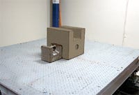
This method is used when calibrating large-capacity scales and it is not feasible to obtain certified weights to equal 80% of capacity. It combines certified test weights and material substitution, and requires class F certified weights of up to 5% of the full capacity, with a means of attaching the weights to the scale. It also requires a means of filling, transporting, and discharging the material to the scale being calibrated. This method can produce accuracies of up to 0.25% of the applied load by performing the following:
• The scale is first calibrated with the certified test weights.
• The test weights are removed and material is added to the calibrated span weight.
• The weight is then recorded and the certified test weights are placed back on the scale and respanned to the material weight plus the test weights.
• This process is repeated until 80 to 100% of the scale capacity is reached.
Hardware Calibration Using Test Weights With Material Build: Step-by-Step Procedure:
1. Follow steps 1–3 of Hardware Calibration Using Certified Weights.
2. Apply the certified weights to the scale equal to 5% of full capacity and span the scale. Record this weight.
3. Remove the certified weights. If the zero indication has changed, repeat previous steps.
4. Add material, equivalent in weight to the span, as indicated on the instrument.
5. While retaining the first increment of substitute material on the scale, add the certified test weights to the scale and set the span. Record this weight.
6. Repeat previous steps until the displayed weight equals approximately 80% of the system capacity.
7. Remove the certified weights and empty all of the material from the scale. Repeat previous steps to check the calibration.
8. Verify the scale by applying a low-capacity certified weight. This checks the system’s sensitivity for possible mechanical restrictions. Apply it at the zero and maximum load points.
9. Record the deviation as the weight is applied and removed. A poor return shows low sensitivity or the presence of mechanical restrictions.
10. If the indicator returns to zero when the scale is emptied, no further calibration is needed.
11. Dispose of the material following local and federal regulations.
Alternate calibration techniques
Using certified test weights equal to 80 to 100% of the scale capacity yields the most accurate calibration. However, conditions for calibrating are often less than ideal:
• Many vessels lack a place to put or attach the required capacity of test weights.
• There may not be a way to distribute the weights equally on (or in) the scale vessel.
• Some vessels are mounted high above the plant floor or in areas offering limited accessibility.
• Some vessels have weight capacities far in excess of the available test weights.
• Multiple calibrations over time can also yield dissimilar results. This can result from different personnel using diverse calibration methods or different test weight quantities, or from placing these weights in different locations on the scale.
|
Scale calibration using test weights with material build |
These real-world issues often produce an error-prone calibration. That’s why some manufacturers have come up with electronic scale calibration, where an operator manually enters the true performance characteristics of each load cell into the weighing instrument from the manufacturer’s certification sheet. In some cases, the instrument can automatically upload these data from a memory chip embedded in the load cell. These data are combined with the instrument’s characteristics to derive the scale’s calibration curve. This method provides accuracies equal to or better than the nonlinearity or hysteresis specifications of the load cells being used (typically 0.02 to 0.03%). This depends on how accurate the data from the load cell’s manufacturer are and how they are transferred to the weighing instrument.
Electronic calibration done right has several advantages: after the scale is verified, any weight discrepancy will indicate a mechanical deficiency in the scale that must be corrected before use. Some wiring problems will also become apparent. Electronic calibration can be easier, quicker, safer, and typically more accurate, without the need for highly skilled labor.
There are many other calibration techniques, some of which use electrical simulation, mathematical computation of weight, or the use of hydraulic jacks and pumps with reference load cells. Both expensive and time consuming, these methods don’t provide the required accuracy. Which calibration you use depends on the size of your vessel, the accuracy or resolution required, time constraints, and available test weights or material.
Scale Components Cable Load points Junction box (also, summing box) The weighing instrument |
Ted Kopczynski is product marketing manager at Hardy Instruments, San Diego, CA. He holds a BS in electrical engineering from San Diego State University and an MBA from National University, San Diego, CA. He has more than 20 years of experience in process weighing. He can be reached at [email protected].
Hardy Instruments designs and manufactures weight controllers and indicators, rate controllers, Allen Bradley–compatible plug-in weigh scale modules, load cells, and bench and floor scales for use in filling, dispensing, batching, blending, check weighing, IBC, and level-by-weight applications. For more information, call 800-821-5831 or visit www.hardyinstruments.com.
About the Author(s)
You May Also Like


