May 25, 2017

Most manufacturers use a Quality Management System (QMS), such as ISO 9001, to ensure their process measurement devices, including industrial tank, floor, platform, and bench scales, are properly maintained (i.e. calibrated and validated). To meet ISO requirements, weighing systems require that Standard Operating Procedures (SOPs) be followed during maintenance. These SOPs document and control how calibrations need to be performed and how results are to be logged.
This article discusses two methods of complying with these requirements. First, is the “traditional” method that requires calibration weights be loaded on the scale on-site in the plant; second, a “smart” method based on factory pre-calibrated load cells that does not require test weights to be loaded on-site, in the plant.
Requirements of ISO 9001
This excerpt from section 7.6 of the ISO 9001 guidelines regarding the Control & Monitoring of Measurement Equipment states:
“Where necessary to ensure valid results, measuring equipment shall:
a) be calibrated or verified, or both, at specified intervals, or prior to use, against measurement standards traceable to international or national measurement standards; where no such standards exist, the basis used for calibration or verification shall be recorded (see 4.2.4)
b) Be adjusted or re-adjusted as necessary
c) Have identification in order to determine its calibration status
d) Be safeguarded from adjustments that would invalidate the measurement result
e) Be protected from damage and deterioration during handling, maintenance, and storage.
In addition, the organization shall assess and record the validity of the previous measuring results when the equipment is found not to conform to requirements. The organization shall take appropriate action on the equipment and any product affected.
Records of the results of calibration and verification shall be maintained (see 4.2.4).”
The most important phrase in the guidelines is bolded and will be discussed in more depth later in this article.
The Elements of an Industrial Scale
To understand the logic behind and benefits of both calibration methods, we must understand the three basic elements of industrial scales:
1. Strain gauge load cell(s), specifically the load sensing devices. Typically three or four are used for a tank, vessel, hopper, or platform scale. The capacity of each load sensor can range from a few grams for small containers to 600,000 lb for large tanks or silos.
2. A junction box, also called summing card, is required when multiple load cells share a single load. The junction box aggregates the millivolt signals from each individual load cell and passes these small voltage changes to the weighing instrument, which can typically measure and resolve incremental changes as fine as 0.15 microvolts.
3. Instrument (weight transmitter, weight controller, weight processor or PLC plug-in weight module). The weighing instrument reads the aggregated signals from the load cells often providing signal conditioning, process monitoring, diagnostics, or control functions based on the weight measured.
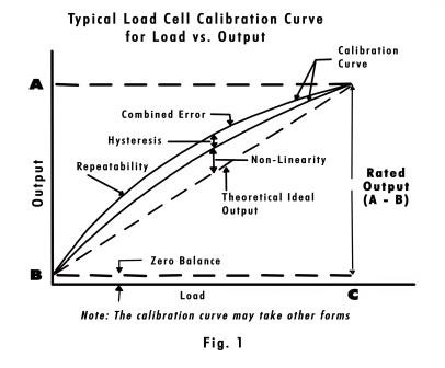
It would be nice if strain gauge load cells performed in a perfectly linear fashion (i.e. their output was a perfectly straight line such as the dashed line in Fig. 1). However this is not the case. Each load cell has its own “unique” output curve across its designed load range (typical output curves seen as the two solid lines in Fig. 1, shows how/where errors are introduced).
In simple terms, calibrating a load cell or system of load cells, informs the instrument what output to expect at two or more points on the “unique” curve of the load cell or load cell system, so it can accurately interpolate the weight applied across the entire capacity range of the scale.
1) The Traditional Calibration Method
The traditional method used to calibrate and validate industrial scales can be very time consuming, costly, disruptive to production, and/or place employees and the manufacturing supply chain at some risk. Usually the higher the capacity of the scale, the greater the impact to people and production.
The traditional method requires the following steps:
1. Installing, connecting, and configuring the scale: load cells, junction box, and instrument.
2. Trimming the individual load cell millivolt outputs, using a traditional junction box with trim pots
3. Using the weighing instrument, capture the zero point (the summed millivolt signal from the junction box, with tank or platform scale “empty”).
4. Using the instrument, capture the span i.e. the summed millivolt signal with test weights loaded equal to or greater than 80% of the max scale capacity (preferably 100%). In many higher capacity scales, for example above many thousand pounds, this may not be feasible because:
• There are not enough “available” certified test weights on site;
• There is not enough “space” to load all the test weights onto the vessel or platform;
• The vessel’s construction may not be “able to sustain” the load of test weight(s) externally;
• The test weights may create a “safety issue” in the work area;
• In these situations some companies may be forced, or elect, to include and/or repeat extra steps in the calibration process. These extra steps are called “weight substitution”. These steps can significantly extend the calibration effort and time and are described in some detail below.
a. Weight substitution involves using a load cell simulator to inject a calculated (approximated) millivolt signal between Steps 1 & 2 to enable a rough “electronic” zero & span capture. Then a manageable “known” amount of certified test weights are loaded onto the scale (say 500 lb) by the person/s doing the calibration, and the weight is then recorded by reading the instrument. The reading would not read the actual weight of the test weights, but an approximate weight of say 509 lb. Even so, the person performing the calibration now knows that a 509 lb reading on the indicator is actually 500 lb. The test weight can then be removed and “substituted” with water or product until 509 lb is again read on the scale. This tedious process is then repeated over and over until the “substitute” weight on the scale is at or exceeds 80% of scale capacity and the span weight is captured. In the case of a 10,000-lb scale the test weight would need to be moved 16 times (loaded eight times and unloaded eight times). This is a widely used calibration method.
b. Some companies may be forced (or elect) to compromise the calibration and complete calibrations with a span load less than the 80% of capacity, thereby deviating from the guidelines laid out for “best weighing practices.” The reason this is a compromise is shown in Fig 2. Using calibration weight point ‘A’ extrapolates further and further away from the actual span at 100%. Using weight ‘B’ on the other hand is far closer to the actual span point.
Positives and Negatives of Using Traditional Method
Positives
1. This method achieves accurate calibration if Steps 1, 2, 3, and 4a (if necessary) are completed correctly.
2. The calibration is traceable to certified test weights and meets the requirements of ISO 9001
Negatives
1. The process usually takes a long time (hours). The larger the scale the longer it takes (hours and hours). This can drive production (OEE) down and cost up.
2. The method masks (hides) any external forces that act on the scale (such as binding) by calibrating them in at zero and span. If these forces increase or decrease at other points on the scales operating range, or are nonlinear, then errors will be introduced.
3. The process can create unsafe conditions for operators and the person doing the calibration from handling test weights or working at heights.
4. The certified test weights, which are usually brought in from outside the plant by a third party, can contaminate the manufacturing area if that have not been thoroughly steam cleaned since being used at another site with contaminants.
2) The Smart Calibration Method
The smart calibration method seeks to deliver all the positives of the traditional method and minimize the negatives. This method approaches the problem on the premise that load cells can and should be pre-calibrated at the load cell manufacturer’s facility, so the customer does not have to complete a lengthy and oft time difficult and dangerous calibration process in their plant. The scale calibration is completed “on-site” using calibration data that is stored in each load cell, then the calibration is verified with a small certified test weight.
Here is how this method works. Immediately after manufacturing, every load cell is loaded with “certified test weights”, to 100% of its designed capacity. The individual performance characteristics (mV/V/ohm) of each load cell are measured and captured. This data is then permanently recorded by storing it in the cloud and on an embedded memory chip located inside the load cell itself. This data is now ready for a weighing instrument to read and reuse it, from anywhere and at any time, specifically at the customer’s manufacturing plant.
To complete the calibration on-site, the instrument first reads the reference weight provided by the person doing the calibration (in the case of an empty scale this would be 0 lb). Second, the instrument reads the “actual” combined millivolt signal (done using the junction box) from the load cells. Third, it then reads the data from the memory chip inside each load cell, which as a reminder was derived by the load cell manufacturer using certified test weights, combines it to compensate for the differences between each load cell (normalizing the load cells). In the last step it uses the data from all three sources to calibrate the scale. This takes only a few seconds. Once the scale has been calibrated, a small certified test weight, usually less than 5% to 10% (depending on the scale size), is loaded for “verification.” This is not a technique unique to industrial scales. This method of pre-calibrating sensors is also used, for example, in smart pressure sensors.
To recap, implementing this method and conforming to a QMS like ISO 9001, the load cell manufacturing process involves the following extra steps (all designed to minimize the number of calibration steps needed to perform to calibrate and/or validate scales on the plant floor):
1. The load cell manufacturer must follow the requirement of the ISO 9001 guidelines (or similar) for the calibration and maintenance of measurement instrumentation and have created and follow their own standard operating procedures.
2. The load cell manufacturer must load the sensors to 100% capacity with certified and traceable test weights, accurate to a minimum of 1 part in 10,000.
3. The load cell manufacturer must measure the output of the load cells with a certified and traceable high-precision microvolt meter, accurate to 1 part in 100,000, which is also calibrated according to ISO 9001 guidelines.
4. The load cell manufacturer must store the calibration data on a chip that is inserted in the load cell that is later retrieved on demand by the weighing instrument.
5. The load cell manufacturer should also store the calibration data in the cloud, for retrieval if required anywhere, anytime.
Now that the steps above have been previously completed by the load cell manufacturer, the smart calibration method now requires only four steps to be complete on-site, at the plant, much less of a burden:
1) The manufacturer must establish and follow a documented standard operating procedure for scale calibrations that meets the requirements of their own QMS (see the example at the beginning of the article for ISO 9001).
2) Install, connect, and configure the scale: load cells, junction box, and weighing instrument.
3) Using the instrument, calibrate the scale without any test weights by capturing the zero point (the summed millivolt signal with tank or platform scale “empty”). The calibration is now complete.
4) “Validate” the calibration with a small certified test weight. For good practice, use 5 to 10% of scale capacity. This may not be feasible with a very large tank that holds, for example 200 tons. People often use less than this range (1 to 2% of capacity) successfully. For best practice, perform the first validation measurement close to the zero point. Later, when the scale reading reaches a higher point (80% of capacity or greater) validate with the small test weight again to verify the scale is weighing correctly at the entire range of its capacity. Note: Correct weight readings should be repeatable to +/-0.1% of total system load cell capacity on systems with no mechanical interference.
Positives of using the smart method (there are no negatives)
1. No trimming is required.
2. The electronic calibration is completed without span test weights in less than 30 seconds.
3. The calibration is traceable to certified test weights and instruments and are permanently recorded and retrievable anytime meeting requirements for a QMS (e.g. ISO 9001).
4. This method helps to sustain or drive production (OEE) up and cost down.
5. This method exposes any external forces that act on the scale when you complete the “validation” step, such as binding.
6. The validation process requires far fewer test weights and provides safer conditions for operators and the person doing the calibration.
7. Contamination can be contained by purchasing a small number of “validating” certified test weights for each manufacturing area (then steam cleaning is not required each time they are used).
Both traditional and smart calibration methods meet the requirements of QMS such as ISO 9001 because both methods use certified test weights and conform to standard SOPs. However, the smart method is faster, less costly and overcomes many of the negatives of the traditional method.
Rodger Jeffery is director of Sales & marketing, Hardy Process Solutions. To learn more about this SMART calibration method and industrial scales, call 858-278-2900, email [email protected], or visit www.hardysolutions.com.
For related articles, news, and equipment reviews, visit our Weighing System & Scales Equipment Zone
Click here for a List of Weighing Systems & Scale Manufacturers
You May Also Like


