
Sign up for the Powder & Bulk Solids Weekly newsletter.
June 17, 2009
9 Min Read
.svg?width=850&auto=webp&quality=95&format=jpg&disable=upscale "Special Aspects of Light-Density Material Weighing")
Light-density materials are typically those materials that have bulk densities under 10 lb/cu ft. These materials are found in many different applications including: tobacco (leaves and additives); forest products (OSB wood chips and MDF wood fines); textiles (polyester fiber); plastics (fiberglass, pellets, and regrind); cereals (bran, oats, rice, and wheat-extruded flakes and additives); and snack foods (potato chips, corn chips, crackers, and popcorn).
When the need arises to accurately weigh and control these materials in process, special attention must be given to the design of the weighing device due to the unique handling characteristics of light-density materials.
Weigh-Belt Design Consideration
|
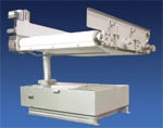
Thayer Model SI-24 Insertion Weigher |
Light-density material weighing requires considerable attention to design details that influence the accuracy and stability of the specific belt-loading measurement (pounds per linear foot), which is dependent on the interaction of various conveyor operating factors and alignments throughout the weighing region of the belt.
An important rule of low-density belt weighing is to maximize scale loading, minimize belt tension, minimize belt beam stiffness, and eliminate as much idler misalignment as possible. Because of the need to address all four of these objectives when dealing with light-density material applications, a well-engineered light-density weigh belt will look sub-stantially different than the more conventional designs typically used in moderate- to high-density applications (e.g., cement industry feeder.) A conventional feeder capable of weighing heavier products (typically 50 lb/cu ft or more) to an accuracy of 0.5% under limited weekly calibration attention is likely to achieve no better than 3–4% accuracy when weighing material with a density of 5 lb/cu ft.
Addressing the problems in sequential order (as shown in Table I) leads to a preferred design.
Belt and Idlers
First, we start with the premise that a relatively thin and flexible flat belt running under the lowest possible tension is the most desirable starting point. Once this is achieved, most everything else will fall into place.
The use of a flat belt and the desire to maximize loading dictates the use of high skirtboards. As with all weigh-belt feeders, the gap between the belt and the bottom of each skirt and the space between the skirts themselves will increase in the direction of flow. This is to prevent material pinch as well as pressure relief as the material moves down the belt.
|
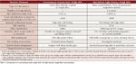
Table I: Comparison of conventional-style weigh belt and light-density weigh-belt characteristics |
Because the chosen belting is to operate under the lowest possible tension and has virtually no beam strength, the idlers that support the belt must be grouped close together so the possibility of belt sag between the idlers and the resulting pinching of product against the belt will not cause incorrect weight measurement. In addition, by eliminating sag, the torque required at the motor drive shaft to
convey the material is lowered, resulting in even lower belt tension.
Because the belt will operate in a near-slack state, the crowning or tapering of the head pulley will have less effect on tracking the belt. Since the belt is light and thin, it cannot be effectively guided using vertical edge–guide rolls. These would accelerate the failure of such a belt. Therefore, a special full-width tracking bar on the return side of the belt is required. As an alternative in some special designs, an active steering idler is positioned on the return strand.
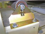
To further reduce the belt tension requirement, the flat idlers should have lower torque requirements than that of standard CEMA idlers. It is important that the idlers turn under no load so that scale calibration of zero can be accomplished to the highest degree possible. Occasionally these idlers will need servicing to ensure that they will turn under no load. Therefore, it is important that the individual idlers can be visually inspected when operating, and can be individually removed and replaced without having to dismantle other conveyor parts. Also, if idlers need to be removed or replaced in the weighing vicinity, some means need to be provided to accurately and precisely adjust their vertical alignments. Note that the individual idler support brackets should be equipped with built-in jack screws to ensure proper belt alignment.
|
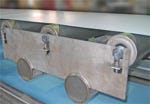
Low-density weigh bridge |
|
Standard removable CEMA idler brackets |
Many low-density materials contain characteristics (strands, irregular chips, and lumps) that cause the material stream (bed) on the belt to develop significant beam strength. The higher the bed depth, the larger this beam effect. To minimize the adverse effects of material beam strength, weigh-belt carrying idlers should be mounted closer together and consideration should be given to increasing both the settling span and the weigh span.
When loading material onto a light-density weigher, it is important that no additional profiling (cross-section shaping) be attempted, since the additional shearing forces build up tension in the belt. This is why it is important to use a metering tube infeed design or charge the weigh belt with a prefeeder of some sort.
Weigh Span
The weigh span of the scale system should be as long as possible to increase the amount of material being weighed, thus reducing the significance of the belt effect errors that occur in the regions of the approach and retreat idler gaps. Also, special attention should be made to the deflection characteristics of the weighbridge used, since it is highly desirable that both the zero-calibration runs and the test-load runs operate under identical alignment conditions. As can be seen from the simplified math model below, it is particularly important to weigh a group of idlers rather than a single idler when the conveyor idlers are intentionally closely grouped. This reduces belt sag and its effects on weighing accuracy.
A simplified math model (Force sensed in pounds):
P= nQL+2Td/L+24EId/L^3
(Neglecting material beam effects)
where:
P = (material load)+(tension/ misalignment)+(belt “beam” effect)
n = number of weigh idlers
Q = lb/in. belt loading
L = approach and retreat idler
spacing (in.)
T = belt tension at weigh idler (lb)
d = misalignment between scale idlers and adjacent idlers (in.)
E = modulus of elasticity of belting (psi)
I = moment of inertia of belt
cross-section (in.^4)
Scale and Load Cell Utilization Factor
|
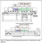
Figure 1: Comparison of low-density-style weigh belt and conventional cement-style weigh belt |
To ensure the highest level of accuracy and the ideal scale configuration, the weight transducer is coupled to a weigh bridge suspension system that prevents extraneous horizontal force vectors (belt tension changes, friction, side loads, torsional forces, etc.) from producing a change in load output. The suspension system should be designed to permit the transmission of vertical force vectors (load) only. Scales that use load cells directly coupled to a weigh idler cannot discriminate meaningful changes in weight from these forces. A good suspension system provides a means to mass counterbalance dead loads so that the load transducer is selected based on net, rather than gross, weighing requirements. This provides up to 100% of load cell resolution to weigh only the light-density material.
Load cell utilization for a cement-style feeder weighing 50–100 lb/cu ft material might typically fall around 20–30% in order to provide adequate overload protection and account for the weight of the belting weigh idler(s). However, on light-density applications, a combination of factors come into play that reduces load cell utilization substantially. These elements include: load cell size availability, relatively higher tare loading (as a percentage of live load) due to the weight of the belting and the weigh idler, and the need for adequate overload protection. Therefore, a cement-style feeder configured to weigh light-density material operates with a load cell utilization factor of <10%, thereby resulting in the “instrumentation system” (load cell and instrument) being three times more sensitive to thermal effects on zero balance. Note that thermal effects on the instrumentation system come from the magnitude and rate of change of temperature. The magnitude of these effects that mainly apply to zero balance (as opposed to span) are inversely related to load cell utilization percent.
Support Structure
In light-density applications, the structural integrity of the entire conveyor structure is of particular significance, extending throughout the weigh bridge itself. Special attention to low-deflecting support structures is a key point in the design. The mass counter-balancing scale permits the use of a heavier and more rigid weigh bridge, which negates the effects of vibration from surrounding equipment and structures and ensures full utilization of the load sensor and increasing its signal-to-noise ratio.
Special Applications
|
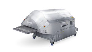
SI Weigher |
For those applications where space is at a premium, a short conveyor—totally supported by a scale—can be effectively used as a light-density weigher. By supporting the entire conveyor, as opposed to weighing a section of the belt, the belting influence factors (belt tension/misalignment, mistracking, belt beam effects, sliding friction, stiffness, etc.) can be eliminated. Where belts are lightly loaded, these effects can seriously degrade accuracy. Since load measurements are not affected by the physical characteristics of the belting and its support, the construction of the belting and its material can be chosen on the basis of durability and belt-tracking ability, without concern for accuracy compromise.
The conveyor portion is suspended from the scale on an open cantilevered “C-frame” pipe support, which greatly simplifies belt removal and replacement for washdown applications. Because the belting is more robust than that used for “under-the-belt” load-sensing weigh belts, and because the belt is positively tracked using a V-guided tracking system, the operating life of the belt is longer than with conventional designs.
The scale design must be the same configuration as used in conventional light-density weigh belts, utilizing mass counterbalancing to eliminate the weight of the conveyor section so that the load cell is sized based on net loading of material rather than gross loading of material and conveying structure.
Conclusion
Many factors affect the ability of a weigh belt to accurately measure and control light-density materials in industrial environments. Specific attention to conveyor design, scale design, and numerous other factors, play a role in determining the ability of a weigh belt to correctly handle light-density materials.
Thayer Scale–Hyer Industries Inc. (Pembroke, MA) is a developer of continuous weighing and feeding equipment for the dry solids conveying and processing industries. Thayer’s belt scales and weigh feeders cover an extremely wide range of applications in virtually all industries that involve dry solids conveying and processing. Thayer Scale equipment provides the rare combination of measurement precision and extreme robustness. For more information, call 781-026-8101 or visit www.thayerscale.com.
You May Also Like
Editor's Choice

.svg?width=800&auto=webp&quality=80&disable=upscale)