Sign up for the Powder & Bulk Solids Weekly newsletter.
May 26, 2009
6 Min Read
.svg?width=850&auto=webp&quality=95&format=jpg&disable=upscale "Choosing a Solids Processing Spherical Disk Valve")
By Jim Lenihan
Solids and slurries have completely different flow characteristics than liquids and gases, so it pays to take a little extra time when choosing a valve for powder applications. This article will review the design principles of the spherical disk valve.
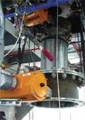
|
Spherical disk valve |
Related to a full port ball valve, this design uses a spherical disk section (segmented ball) to provide shutoff. Imagine taking a sphere from a ball valve and removing 80% of it. You are now left with a spherical-shaped disk sized to cover the full port opening. Mounting arms are added to provide a pivot on shafts through the center axis of the original ball. A section of the spherical disk seals against the identical spherical radius of the seat, while the rest of the shutoff surface is undercut below the spherical radius.
The advantages of this design are:
1. The spherical disk rotates 90° out of the material flow to allow mass-flow through its full port.
2. The undercut disk segment provides clearance that prevents powder from jamming between the disk and housing.
3. The spherical disk wipes the material away from the matching radius of the seat to provide sanitary sealing and longer seat life.
The following are some of the factors to consider when choosing a spherical disk.
Material of Construction
The powders and solvents to be processed will dictate the product contact material. Cast iron, carbon steels, and aluminum can be used for many industrial applications. Corrosive processes call for the use of stainless steel and, in some cases, material laden with solvents or other corrosives will justify the extra expense of using Hastelloy or other high nickel alloy to prolong valve life.
For stainless-steel valves of welded construction, Type 316L grade is preferred. It is more corrosion-resistant than Type 316 stainless steel and the lower carbon content prevents carbon precipitating from the welded joints.
Seat Material
Extremely abrasive material will tend to dictate using metal seats versus the more commonly used reinforced Teflon seats. The metal seat will give longer life and can be used at higher temperatures than Teflon, but the shutoff sealing is limited to dust-tight, ANSI Class IV, or ANSI Class V. Reinforced Teflon and some other resilient materials can be used up to 450ºF, and provide Class VI shutoff for pressure-assisted sealing. Pressure-assisted sealing is when the process pressure or vacuum is used to push or pull the shutoff disk into the seat. The extra cost of inflatable seals is justified for bidirectional sealing.
Cleanability
The sanitary requirements of the process will govern the surface finishes and other sanitary options. Finishes are defined as follows:
No surface finish (Ra) specified; sometimes referred to as “mill finish” or “as cast.” Fabricated valves will have internal welds that are ground smooth and flush. This is common in general industrial applications where cross-contamination or cleanability are not a concern.
#2 finish: Ra 33–65 microinches. 150–180 grit. Also referred to as “buffed, blended, or uniform appearance finish.” This is often specified for the outside of equipment that will be washed down.
#4 polish: Ra 16–32 microinches. 180–240 grit. All fabrication and handling marks are removed and the surface is buffed to a uniform satin finish. The #4 polish is typical for the interior of equipment
that needs to be cleaned between batches to prevent cross-contamination.
#7 polish: Ra 10–15 microinches. 240–320 grit. All surface imperfections are repaired. This type is often referred to as “pit free” and “mirror finish.” It is used for high-purity applications such as processing potent pharmaceutical actives. It is also used for products that tend to adhere to surfaces.
For automatic cleaning, spray balls or jets should be considered. Another option is a valve that can be dismantled by hand for inspection and cleaning. For safety reasons, the size of such valves are typically limited to a 10-in. port diameter due to the weight of individual components.
Weight
The weight of a valve is especially important for mobile or rotating equipment. High-performance and heavy-duty models can weigh four times as much as their regular-duty counterparts. Dust-tight, full-vacuum, and 1-bar service is considered to be regular-duty service (90–150 psi is high performance). An 8-in. manually operated regular-duty valve can weigh 55 lb versus nearly 200 lb for an 8-in. high-performance model.
Mounting Arrangements
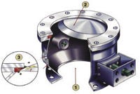
|
1. Full port opening eliminates bridging |
ANSI and DIN bolting patterns are used as industry standards for heavy-duty and high-performance models. Quick clamps can also be used for applications up to 30 psi and port sizes up to 8 in.
Some valves will include blind tapped holes, which may be a problem if the valve is mating with existing blind tapped holes. Another option is to choose oversized flanges, which allows for through holes. For regular-duty service valves, ANSI and DIN bolting patterns can be overkill; alternative bolting patterns are available.
Actuation
As with other quarter-turn valves, levers, gear drives, or chain operators are available. Pneumatic and hydraulic operators are available in double-acting or fail-safe modes. Pneumatic operation should be the first choice for price, reliability, and speed. When handling solids, a higher factor of safety is used to calculate seat torque requirements. The factor is typically 1.5 instead of the 1.25 used for liquid and gas valve calculations.
For solids that “set-up” or harden, an oversized actuator and specially designed disks that can break through the hardened cake are used. Actuators are typically sized for 80 psi pressure. If the available supply air pressure is dependably higher (100–120 psi) or lower (40–60 psi), this will factor in the sizing of the actuator.
For fail-safe operation, spring return actuators are the norm. When a spring-return type actuator is used, it is oversized to compensate for the spring, as well as the unseating, run, and seating torque required for valve operation. This can lead to weight and space problems, as well as extra cost. An alternate fail-safe option is to use a double-acting actuator with a pneumatic accumulator that is sufficiently sized to close the valve. If there is a loss of pneumatic pressure, a pressure switch activates the accumulator and operates the valve.
Flow Control
Fast-acting (1–5 seconds), quarter-turn valves are ideal for flow control of solids. A pneumatic (3–15 psi) or electropneumatic (4–20 mA) positioner can take a signal from a manually adjusted pressure regulator or from a computer controller. The pneumatic positioner is often used in manually operated filling stations, while the electropneumatic positioner is typical for automatic loss-in-weight systems.
Summary
Choosing the best valve for your powder application will bring many benefits. The payback will be better performance, lower maintenance costs, and better product quality over the life of the processing equipment.
Jim Lenihan is general manager of Gemco Valve Co. (Middlesex, NJ). He has 25 years of experience in the design, manufacturing, and marketing of valves and seals and holds a manufacturing engineering degree. For more information, visit www.gemcovalve.com.
You May Also Like
Editor's Choice


.svg?width=800&auto=webp&quality=80&disable=upscale)