

Sign up for the Powder & Bulk Solids Weekly newsletter.
September 14, 2010
9 Min Read
.svg?width=850&auto=webp&quality=95&format=jpg&disable=upscale "Not All Fail-Safe Rotary Paddle Point Level Sensors Are Created Equal")
By Gregory DeRudder, Monitor Technologies LLC
When looking for new or replacement point level bin indicators, you will likely be comparing sensor features from various equipment manufacturers. Some of these manufacturers have a model available with a feature that is referred to as “Fail-Safe”. Other manufacturers might offer a sensor model depicted to be “Truly Fail-Safe”, “Fail-Safe Plus”, “Self Validating”, “Genuine Fail-Safe Protection”, “Advanced Fail-Safe Protection”, etc. There are definite differences that should be considered during the sensor selection process. For the purpose of discussion, the online Merriam-Webster dictionary defines (in part) the term fail-safe as “incorporating some feature for automatically counteracting the effect of an anticipated possible source of failure.”
|
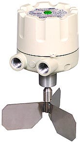
Figure 1: Example of a rotary paddle that has evolved to a "truly fail-safe" sensor |
Generally speaking, for most Fail-Safe level indicators, the term fail-safe refers to the output signal condition that occurs with loss of power to the probe. In the case of point level sensors, this output will generally be provided by the use of relay contacts. It should be noted that a point level sensor that uses mechanically activated simple micro type switches for outputs is incapable of generating a fail-safe output since it can not react on its own in the event of power loss where a relay, if energized, will without any other influence de-energize upon the loss of power causing the relay contacts to revert to their “normal” state. Here is a description of one manufacturer’s fail-safe functionality as stated in its Installation and Operation bulletin for one of its fail-safe capable rotary paddle type of sensors:
1. Fail-Safe High - The relay will de-energize when material is sensed at high level or with power loss.
2. Fail-Safe Low - The relay will de-energize when material is below low level or with power loss.
The implied use would be that the sensor output could be wired in such a manner that if the sensor went into the fail-safe condition, as the relay de-energized, some external device would be powered off or otherwise cause the targeted process to be placed in a safe condition. When the term fail-safe was first applied to level sensors, this was all it did or could do.
To enable fail-safe high or fail-safe low operability, most manufacturers of fail-safe sensors includes some sort of “switch” to select between fail-safe high and fail-safe low as needed for the application. This can be a regular slide or rocker switch or it could be a jumper block (shunt) moved to a specific pair of pins to select the desired functionality. Everything stated so far regarding fail-safe operability also applies to other sensing technologies such as vibratory or RF Capacitance type probes and is not just limited to rotary paddle types.
Now, let us focus on rotary paddle type sensors and examine some newer functions and how they contributed to the evolution of the fail-safe rotary paddle bin indicator. We will see how this evolution has redefined end-user expectations of what it means to be truly fail-safe and what extra functional benefits are available in higher end designs.
|
Figure 1A: A truly fail-safe rotary paddle level indicator installed in a concrete batching plant |
Some time after sensor manufacturers began producing and selling sensors with the previously described fail-safe functionality, the sensor industry decided that it needed detection of level indicator failure for reasons other than loss of power. A few potential causes of failure beyond that of power interruption include motor failure, drive train failure (gears, shafts, clutches, etc.), or general electrical/electronics failure not related to primary power. Any of these occurrences can have costly consequences such as overfilling a vessel, plugged pneumatic conveying lines, material spills, running a process dry of material, etc. Consequently, some level sensor manufacturing companies enhanced their designs to detect and indicate failures beyond that of simple power loss (see Figure 1).
A little more than 10 years ago, when electronics technology evolved to the point that on board decision-making intelligence became affordable, several sensor manufacturers included microcontroller/microprocessor devices to achieve smarter and self-validating sensor designs. In the case of a rotary paddle type of bin indicators, the addition of electronic micro-controllers made it possible to include the use of optical sensors or magnetic Hall Effect sensors to verify other operational functions in order to detect and react to sensor failures beyond that of simple loss of power.
One patented method of verifying motor functionality and drive shaft rotation is to use low-cost Hall Effect sensors to check for the presence or absence of drive shaft rotation (see Figure 2). A ring magnet with multiple magnetic poles is attached to the drive shaft and these magnetic poles will be detected by a Hall Effect sensor as the drive shaft rotates. Other designs use a photo-interrupter attached to the drive train used in conjunction with an optical encoder transceiver. As the paddle shaft rotates, the photo-interrupter (a slit mask or flag) will intermittently block a light source, usually infrared, from being received by the receiver portion of the optical transceiver. In either design, the microprocessor controller can be programmed to expect an output from the Hall Effect or optical sensor at a fixed frequency. If the microprocessor does not receive the output within the window of time allowed, it can perform other queries to determine whether or not a failure has occurred. Once a paddle is sufficiently covered by material, shaft rotation will cease. When the microprocessor determines that shaft rotation has ceased, it will check other conditions within the sensor to determine whether or not the absence of rotation is being caused by the presence of material or by some sort of failure. On one popular sensor design that uses magnetic Hall Effect sensors in place of optical sensors, when paddle rotation has stopped due to the presence of material, a spring loaded internal actuator assembly will continue to rotate until a small magnet aligns with and causes a second Hall Effect sensor to indicate that there is a presence of torque on the drive shaft. This would indicate the presence of torque on the paddle shaft.
With these two pieces of information about the presence or absence of shaft rotation and the presence or absence of torque, the micro-controller has enough information to make an intelligent determination regarding the health of the device. If there is rotation, all is well. If there is no rotation and shaft torque is detected, all is well. But, if there is no rotation and there is no torque detected, then there is something wrong with the overall sensor and the microprocessor will report this through a fault relay and cause the material sense relay to default to the fail-safe position. A design using optical sensing technology could be used in the same manner as described for the design using Hall Effect technology to sense torque but there are other methods that might be used. For example, one could conclude that if there is no shaft rotation yet the material sense relay is indicating the presence of material, proper internal circuitry could lead the microprocessor to the conclusion that the sensor is functioning correctly.
|
Figure 2: Cutaway of a “truly fail-safe” level indicator with Hall-Effect sensors |
So is one better off with magnetic or optical sensing technologies in a microprocessor equipped rotary paddle bin level indicator? There are two fundamental problems with most optical encoder designs. First, it does not take an extreme amount of dirt to block the transmitted light. Condensed vapors can also inhibit the ability of an optical sensor to function. Secondly, ambient light (usually sunlight) may cause the sensor to see the presence of light and react accordingly even if the photo-interrupter flag is physically in position between the transmitter and receiver portion of the optical device when the enclosure cover is removed for inspection or for some other reason. A better sensing technology than optical for this type of application would be to use magnetic Hall Effect sensors to indicate both the presence or absence of rotation and the presence or absence of torque. Hall Effect sensors are not affected by dust, moisture, or ambient light and add a greater margin of reliability over that of optical type sensors.
Everything discussed up to this point (relay output signaling regarding fail-safe failure indication plus normal material presence or absence of material) can be accommodated with a single relay output. The problem with a single relay solution is that there is absolutely no differentiation between fail-safe indication and material sense indication as indicated when the output relay is de-energized. In order to be able to differentiate between a sensor failure and material sense indication, many manufacturers added a second relay to act as an alarm indication that would react without any regard to material conditions in the vessel being monitored. A standard practice is to have the fail relay be energized during normal operation so that it would de-energize on any failure concluded by the micro-controller as well as upon the loss of power to the bin sensor.
The term “fail-safe” as originally promoted years ago is still a valid term. However, technical advances have allowed new self-validation functions to be economically included in modern designs and have, by default, re-defined the term to “truly fail-safe.”
So, if you find yourself in the market for a point level sensor and you are looking at a model that claims to have “fail-safe” attributes, you might better serve yourself by selecting a unit that includes self-validation of all electrical and mechanical functions and not a unit that simply de-energizes a relay if and when power is lost. Yes, such a unit will cost a little more money, but the potential savings of clean-up costs following an over-fill condition easily justifies the additional expense. But, no matter what sensor you choose, remember that every fail-safe indication in existence is useless unless your control system can recognize and appropriately react to a failure indication. The functionality has to be part of your system design in order to work.
Gregory DeRudder is a product manager for Monitor Technologies LLC (Elburn, IL) and has been with Monitor for more than 11 years. DeRudder has a Bachelor’s Degree in Electronics Engineering Technology from the DeVry Institute of Technology (Chicago).
You May Also Like
Editor's Choice


.svg?width=800&auto=webp&quality=80&disable=upscale)