
Sign up for the Powder & Bulk Solids Weekly newsletter.
September 14, 2010
4 Min Read
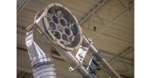
.svg?width=850&auto=webp&quality=95&format=jpg&disable=upscale "Feeding Low-Melt Materials with Screw Feeders")
Todd D. Messmer
[email protected]
|
Todd D. Messmer |
Several types of low-melt materials can be successfully fed with a traditional screw feeder when designed with the proper features.
First, let’s take a look at the feed screw and nozzle diameter. These are going to be the major product contact components that can potentially generate heat due to the feed screw shearing the material. Let’s look at the basic design principle of the screw feeder. The throughput of a screw feeder is designed around the amount of water volume in one flight of the feed screw. Multiply this volume by the rpm of the feed screw and you get your feed rate per hour. By simply moving to a larger diameter feed screw and nozzle, the rpm of the feed screw can be decreased along with the amount of energy (friction) the feed screw is introducing to the material. For example, take an application feeding wax powder weighing 38 lb/cu ft at a rate of 1000 lb/hr. Using a screw feeder with a 2.25-in. feed screw (theoretical water volume of 0.3 cu ft/revolution), we would hit this rate at 88 rpm. Eighty-eight rpm on a wax material could be enough to cause the material to melt due to the friction of the feed screw. By increasing the diameter of the feed screw to 3.5 in. (theoretical water volume of 1.12 cu ft/revolution), the rpm of the feed screw can be decreased from 88 rpm to 23 rpm.
Screw feeder manufacturers will have optimum operating ranges with respect to the controller VFD (AC motor) output (hertz), motor reducer combination, and resulting feed screw rpm. In the previous example let’s assume that an 1800-rpm AC motor will operate at full speed with the VFD at 60 Hz. Reducing the motor rpm by 10:1 will provide 180 rpm at 60 Hz - approximately 3 rpm/Hz. Using this formula, at 23 rpm we could expect the VFD to be operating at 7.67 Hz. If this Hz value (actual motor speed) were too low, you could change the reduction from 10:1 to 40:1 and in turn increase the VFD Hz value (actual motor speed) from 7.67 to 31.33 Hz. (1800 rpm reduced by 40:1 = 45 rpm at 60 Hz = 0.75 rpm/Hz = 31.33 Hz at 23 rpm). The end result is achieving the same feed screw rpm at a faster motor speed without running the risk of overheating a fan-cooled AC motor.
There is one other area in a screw feeder that we need to pay attention to when feeding low-melt materials. This is the area where the feed screw physically connects to the drive motor. Some feeder manufacturers will call this area the “quill”. The main component of the “quill” is the drive hub, which typically has an external thread cut onto it. The drive hub transfers the rotational energy of the motor to the feed screw via (typically) an internal thread cut into a “driver”, which is welded to the feed screw. This system allows you to disconnect the feed screw from the feeder for servicing and cleaning. The “quill” should contain some type of sealing system to protect the rotating drive hub and “driver” from introducing friction to the material as well. This area needs to either be purged with instrument quality air or designed with some other system (i.e. flighted driver) to keep the material away from and out of this sealed area. A flighted driver operates basically the same as a feed screw as it “feeds” the material out of the sealed area and into the flights of the feed screw.
Ultimately, if you are looking to feed low-melt materials, don’t rule out the traditional screw feeder. If designed with the proper features, a screw feeder can offer trouble-free feeding of these materials. As with any bulk solids material and feeding equipment application, ask the manufacturer of the equipment about material testing. Material testing is often free of charge and can save you thousands of dollars and weeks of downtime from selecting the wrong piece of equipment for your application.
Todd D. Messmer is a senior applications engineer for Schenck AccuRate (Whitewater, WI).
You May Also Like
Editor's Choice


.svg?width=800&auto=webp&quality=80&disable=upscale)