Sign up for the Powder & Bulk Solids Weekly newsletter.
September 26, 2008
12 Min Read
.svg?width=850&auto=webp&quality=95&format=jpg&disable=upscale "Sieve-Testing Standards, Certification, and Calibration")
By Arthur Gatenby
|
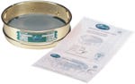
Mesh-certified sieve |
Sieving in its most elemental definition is the separation of fine material from coarse material by means of a meshed or perforated surface. The technique was used as far back as the early Egyptian days as a way to size grains. These early sieves were made of woven reeds and grasses. Today the sieve test is the technique used most often for analyzing particle-size distribution.
Although at first look the sieving process appears to be elementary; in practice, there is a science and art involved in producing reliable and consistent results. In order to better understand sieving, there are several areas of sieve specification that should be explained.
What Are Test Sieves?
Test sieves are measuring devices used to determine the size and size distribution of particles in a material sample using wire mesh of different openings to separate particles of different sizes.
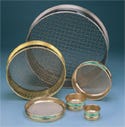
Test sieves usually consist of wire mesh held in a frame. In most laboratory applications, the frame is round and is made from stainless steel or brass. The standard frame sizes are 3-, 6-, 8-, 10-, or 12-in. diam and their metric equivalents. The woven mesh can be made of stainless steel, brass, or bronze. For most applications stainless steel is the most common material used.
What Are the Limitations of the Test Sieve Procedure?
The main limitation with the construction of test sieves is the inherent nature of a woven product, including control of sag when mounted and the uniformity of construction of the holding frame. It is also essential to maintain consistent sizing across all the openings in a piece of mesh.
Because of the inherent variations of openings in any woven product, there are limitations to the degree of uniformity achieved in the opening size across the mesh in a sieve. This results in a practical limit to the range of openings and to the precision of results from a specific sieve.
The sieve test requires particles to pass through the sieve mesh. The practical limit for using a test-sieve procedure is a particle size of 20 µm.
What Are the Test-Sieve Standards?
The first sieve-testing standards were developed by W.S. Tyler Co. before 1920. This original work predated any published activity by the standards organizations, and the Tyler designation is the de facto standard in many industries. In 1925, ASTM International prepared the official standard for Test Sieve Size, Test Sieve Construction, and Test Sieve Mesh in the United States. European standards were developed by a German university group in 1977 and are known by the designation DIN 4188. These were followed by British Standards (BS 410). The international standards (ISO 565) were developed by the International Standards Organization in Europe. They were designed to be the universal international standards. However, in practice, all of the aforementioned standards are in operation.
Sieve-testing standards relate to the construction of the sieve frame and mesh mounting as well as the tolerances allowed in the variability of mesh openings. Basic principles are common to all of the standards, and variations in terminology and details are small. These small differences, however, can often lead to confusion. The following is a synopsis of the principles behind these standards.
1. Rigid construction
2. Cloth (mesh) mounted without distortion, looseness, or waviness
3. Joint between mesh and frame to be filled or constructed so that particles will not be trapped
4. Frame made of noncorrosive material, and must be seamless
5. Bottom of the frame sized to easily slide into the top of same-sized sieve, thus enabling stacking
6. Cloth opening to be a minimum of 0.5 in. less than nominal diameter.
The wire cloth (mesh) standards include the following list of nominal size openings in inches, millimeters (microns), and sieve number. The following specific dimensional examples come from the ASTM E11 standard.
1. Permissible variation of average openings (depending on opening size and ranges from ±2.9% of nominal size for 125-mm mesh to ±15% for 20-µm mesh)
2. Not more than 5% of the openings can exceed 1.04 times the nominal size for 125-mm mesh, to 1.45 times the nominal opening for 20-µm mesh.
3. Maximum individual opening (for any opening) ranges from 1.0472 times the nominal size for 125-mm mesh to 1.75 times the normal mesh for 20-µm mesh.
4. Wire diameters are specified and range from 8 mm for 125-mm mesh to 0.020 mm for 20-µm mesh.
More recently, methods based on laser and energy technologies, sedimentation techniques, image analysis, and centrifuge-type methods have gained acceptance. However, procedures using test sieves are still widely used. The sieve-test result remains the basis or standard against which newer techniques are checked. In addition, the equipment cost for the test-sieve procedure is significantly lower than the capital investment needed for newer methods.
What Are Sieve Certifications?
|
Sieves |
Sieve certifications are statements that a test sieve meets or exceeds published criteria. It is an assurance that a new sieve will perform in a predictable way. The closer the tolerance required in a manufacturing process, the higher the level of certification needed. Similarly, a master set of test sieves against which working sieves (sieves in everyday use) are checked for wear and predicted performance need a high level of certification. When test sieves are part of a process that is required to meet traceability prerequisites, such as a specific ISO level, a certification will document the needed traceability.
Many sieve manufacturers provide a certificate that states that the sieve was manufactured in conformance with a specific standard (e.g., ASTM, ISO). This Manufacturing Conformance Certificate does not reference nor does it certify conformance of the mesh. Most manufacturers supplying a Conformance Certificate will analyze the mesh and provide a mesh certification for an extra charge.
A mesh-certified sieve will be provided with a certificate that states the sieve was manufactured in accordance with a specified standard and submitted for laboratory analysis, and is certified to conform to that specific specification/standard (e.g., ASTM, ISO).
There is a third level of tolerance that certifies that the manufacturing standard is met and that the mesh was submitted for lab analysis. It also certifies that its openings fall in the middle of the specific standard/specification (e.g., ASTM, ISO). This is effectively a 30% better tolerance than the mesh of a fully certified sieve. This is known as a mid-point sieve.
These three levels of sieve certification enable the comparability of performance of one sieve to another of the same size.
Until the development of the mid-point Sieve, high levels of comparability were achieved by providing sieves that were optically matched to a user’s standard sieve. A time-consuming and costly procedure was needed to accomplish this level of comparability, and the results were not significantly better than those achieved using mid-point sieves.
Mesh-certified sieves, mid-point sieves, and sieves carrying the Manufacturing Conformance Certificate are all made with mesh that already conforms to official standards. However, there are three lower grade levels of sieve mesh available when tolerance levels are not as stringent.
The first is Market Grade. These sieves have a weave that uses a larger-diameter wire resulting in a high-strength square-mesh cloth suitable for general-purpose screening. There is no official standard for Market Grade test sieves. The second, Mill Grade, is a class of woven mesh using smaller wire that results in larger open areas in the screen mesh. There is also a Twill Weave, in which the weft and warp wires alternatively run over and under two wires rather than over and under alternate wires as in standard mesh. As none of these has official standards against which to measure the expected performance, none of these is provided with a mesh certificate.
Sieve Calibration
|
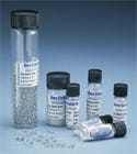
Calibration-bead set |
Quality control of the sieving process is essential, and for people involved in material processing and particle characterization, sieve calibration can be a confusing topic. It is beneficial to understand what sieve calibration is, why a working sieve should be calibrated, and how to calibrate a sieve.
What Is Sieve Calibration? Sieve calibration is the process of checking a working sieve’s performance. (A working sieve is a test sieve that is used regularly to perform a particle-size analysis.)
|
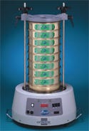
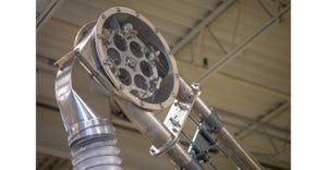
Typical sieve shaker |
Why Calibrate a Working Sieve? Since working sieves are used daily for tests, they are also cleaned regularly. Although frequent use can cause changes in mesh openings, much of the damage sustained to working sieves occurs during cleaning. Often, the operator hurries to clear the mesh of residual particles by strongly tapping the frame. This tapping can distort the mesh. Operators also use brushes to remove residual particles after a test. This process often distorts sections of the sieve mesh. These alterations of the sieve will change the results obtained in subsequent tests, hence the need for calibration.
Excessive damage, such as tears or large distortions of the mesh weave, can be detected by visual inspection. Damaged sieves can be taken out of service when the damage is observed. When the change is small, visual observation may not detect a variation in the test results attributable to the sieve’s change. A way to determine if changes have occurred is to compare the sieve’s performance against a known standard. This is sieve calibration.
In addition, in operations with tight particle-size specifications, calibration of new test sieves is performed to establish a performance baseline for the sieve.
How Is a Test Sieve Calibrated? The base point of a sieve calibration process is the use of a fixed standard and there are a number of approaches used. The most common is the use of a master stack of sieves, a master sample, or calibration spheres or beads.
A master stack of sieves includes one of each of the sieves used in the processes. A master stack should consist of mesh-certified sieves. In the event of tight tolerances for the sieve tests, it is recommended that mid-point sieves be used. The following steps are used for this method:
1. Prepare two samples of the material selected for the calibration process.
2. Place the master stack of sieves on a sieve shaker.
3. Load one of the samples into the top sieve.
4. Run on a sieve shaker for the predetermined time.
5. Prepare a percent-retained analysis of the result.
6. Place the stack of working sieves (sieves with sizes to match master stack).
7. Repeat steps three through five for the second sample of the material.
8. Compare the results of the two analyses.
9. Check variance from the master stack against acceptable tolerances.
10. Replace the working sieves that are out of tolerance.
11. Some users only calibrate one sieve at a time and compare it to one sieve from the master set. This procedure can be done before putting new working sieves in service.
12. In some processes, master samples are maintained of all material that is subject to sieve testing. The results expected from working sieves were established through the use of a master sieve stack or other calibration techniques. In this method, a sample from the master is used and the following steps are taken:
1. Place the stack of working sieves to be checked on a sieve shaker.
2. Load the selected sample from the master sample into the top sieve.
3. Run the sieve shaker for the predetermined time.
4. Prepare a percent-retained analysis of the result.
5. Compare the results to acceptable tolerances for the sieves in this stack.
6. Replace the working sieves that are out of tolerance.
The used sample may be returned to the original master sample. Depending on the type of material, deterioration may occur during the sieve test. Where this occurs the test sample is discarded after use.
As with the use of a master stack, some users only calibrate one sieve at a time and compare it to a performance-tolerance chart for that sieve size. This procedure can also be used for new working sieves before putting them into service.
Calibration spheres, in sizes for each of the sieves to be calibrated, are used to determine the actual results obtained by each sieve tested. This method is simple and gives a precise result on the mean aperture size. The result is traceable to NIST and NPL standards. It is a good check for standards reporting and for setting internal standards. The procedure for this calibration is as follows:
1. Select the sieve to be calibrated.
2. Empty the contents of the bottle containing the appropriate standard onto the sieve.
3. Shake evenly over the surface for one minute.
4. Calculate the percent passing through and read the mean aperture for a calibration graph.
The method specified by ASTM is to optically inspect a sample of the openings, measure the apertures and the wire, and compare the results with the ASTM E11 standard. Traditionally, this has been accomplished visually using a microscope. However, there are new computer-based image-analysis systems that are beginning to have limited use for sieve calibration.
Summary
Sieves have a long history as the base for measuring and analyzing particle size in material. In spite of the advent of new technology-based methods, procedures based on sieves continue to be the main basis for particle-size determination. In order to produce reliable and consistent results, it is evident that sieving requires an understanding of not just one, but a combination of integral factors such as test sieves, limitations of the test-sieve procedure, test-sieve standards, sieve certifications, and sieve calibration.
Arthur Gatenby is president of CSC Scientific Company, Inc. (Fairfax, VA) and can be reached at [email protected] or 703-876-4030. CSC specializes in the development, production, and distribution of equipment used to measure moisture, particle size, and surface tension. For more information, visit www.cscscientific.com.
You May Also Like
Editor's Choice

.svg?width=800&auto=webp&quality=80&disable=upscale)