Sign up for the Powder & Bulk Solids Weekly newsletter.
December 3, 2018
10 Min Read

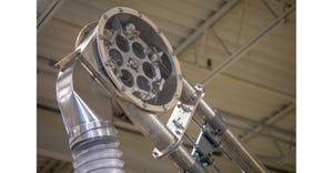
Figure 1. Test piping layout showing standard and inclined pipe sections
As with many technologies related to bulk materials handling, pneumatic conveying can be a mixture of art and science. Along with many tangible physical relationships (i.e. pressure, airflow, and velocity) there are also several “rules-of-thumb” that drive industry know-how. A few such rules relate to the layout of piping that will make its way through the facility:
Choose the most direct route – shortest distance and fewest elbows
Avoid back-to-back elbows
Run pipe horizontally or vertically – avoid inclines
The last one regarding inclined pipe is probably the least understood and is sometimes at odds with the other recommendations. The most direct pipe routing will yield the lowest operating pressure and energy consumption. Provided there is a clear path for the pipe, an incline would be more direct compared to any vertical and horizontal run. Likewise, for small changes in vertical height, two elbows will need to be close to each other (back-to-back). The way to overcome this is to use an inclined pipe in its place. Since contradictions are unavoidable, logic suggests a lesser of two evils approach. Whichever violation provides the least negative impact would be the preferred choice. The difficulty is knowing how to evaluate this comparison if inclined pipes are not well understood. To help answer this question, research was conducted to assess both the viability (when to use it) and the impact (how to account for it).
Background
Since no two applications are exactly the same, each piping system will be unique with some level of customization to the general routing, avoiding obstructions and a preferred path to end up at the correct elevation for the destination. Generally, pipes are more easily supported when laid horizontally or elevated straight vertical due to the interactions with the steel. They also display better in drawings and isometrics, so designers will normally gravitate toward this practice. However, when encountered, obstacles, tight spaces or subtle changes in elevation or direction may require other solutions to be implemented. Subtle changes (such as a 3-degree angle) have little impact on the system so the angle must be significant to warrant special consideration. An inclined pipe may be considered in three ways:
1) Horizontal pipe rising more than 10 degrees*
2) Vertical pipe angling more than 10 degrees
3) Horizontal pipe declining more than 10 degrees
* the threshold angle ranges from 7 to 15 degrees depending on the source
Primarily, we will deal with the first case of a horizontal pipe that rises at an angle greater than 10 degrees up to and including a 45-degree slope. Above a 45-degree slope would technically fall into the second category of an angled vertical, but we can trust that the learnings will extend into this realm to some degree. In both these cases, gravity is working against the effort to move the material either horizontally or vertically. In the vertical arrangement the travel is directly opposed to the gravitational force. If the air velocity is above the aerodynamic terminal velocity of the material, then it will elevate with the associated rise in potential energy. In the horizontal arrangement the particles oppose gravity indirectly either by creating lift and entraining the particles (dilute phase) or allowing the particles to rest on the pipe bottom and overcoming the weight friction. When the pipe is inclined at an angle, it would seem both mechanisms are in play, but to varying degrees depending on the angle and the material characteristics. In the third scenario gravity is assisting in the flow of material as it moves through the pipe. Initially as the angle gets steeper it aids the horizontal movement. Eventually the decline angle will be greater than the slide angle of the material with the pipe wall and the material would flow with or without the airflow present. For this reason, we can eliminate the third case (declined piping) as a concern and focus on inclined piping.
Experiment
An experiment was created to analyze the case of the inclined pipe as compared to a traditional piping layout. In Figure 1, we can see the feed point for a pneumatic conveying system using an airlock fed by a weigh belt. The piping after going horizontal for a short distance then takes two routes to get to the same destination – one of which is a 21-degree slope for 50 ft. By using the same feed source and routing the material through the same connecting point and operating at the system similarly we get a close comparison for analysis. Four materials were selected that have a range of density and particle size (See Figure 2). These materials were handled in either dilute phase, dense phase, or both. Two different rates for each condition were targeted.
See Figure 1
In addition to normal conveying data (airflow, pressure, rate) the convey line was outfitted with pressure transmitters along the way to yield more definition as to convey losses in the area. We can see the overall pressure drop for the “section” which includes getting the material from the feedpoint to the joining point (P1-P3). For this comparison, the inclined pipe has a shorter overall length of pipe (think hypotenuse on a right triangle) and one less 90-degree elbow. We can also see the pressure for the “segment” which is equal lengths of pipe that is inclined or level horizontal (P2-P3). In this way we can see the correction factor for different types of flow.
Dense phase flow in this test was primarily generated using continuous dense phase equipment (airlock fed) to record steady state conditions. Alternatively, the natural sugar product was conveyed using a batch dense phase vessel along with supplementary downstream air injection. Multiple batches were conveyed and the values for each run averaged. While important to demonstrate the inclined pipe can be used on various feed devices, the resulting data is comparable to the others runs using steady state.
See Figure 2
Results and Analysis
Once the data is collected we can begin to understand more about how the inclined pipe approach compares to standard horizontal/vertical piping and how we should account for the inclines in system designs. There are three scenarios that could result since the inclined convey pipe run is technically shorter in distance than the standard (14 ft and one elbow less):
Net Benefit – The benefit of the shorter length is greater than the detriment of using the incline
Null Effect – The benefit of the shorter length balances out the detriment of using the incline
Net Detriment – The detriment of the incline outweighs the benefit of the shorter length
The results of the various convey runs can be found in Figure 3 and are summarized here by material.
Glass Filled Pellets
The section results for the “fiberglass filled PE pellets” was null effect for both dense phase and dilute phase. Approximately the same pressure drop was observed in both piping arrangement for both the high and low rates. In the segment results, the incline required 2-2.5x the pressure drop compared to the horizontal pipe. The dense phase airflows were identical, while the dilute phase runs required 11-15% more airflow/velocity to keep material moving efficiently up the incline depending on rate (low rate 11%, high rate 15%). Qualitatively the pellets saw good slug formation through the inclined section in dense phase with very little material sliding down the incline. In dilute, the airflow had to be increased to keep material from dropping out of suspension. Once saltation occurred, the system had great difficulty trying to recover. The slide angle was measured at 35 degrees.
Green Coffee Beans
The section results for the “green coffee beans” showed a net detriment in both dense and dilute phase. The segment results showed the incline pressure drop to be 4.5x higher than the horizontal in dense phase and 2-2.3x higher in dilute phase. The airflow for dense phase increased a dramatic 35-45% while the dilute phase airflow required only increased 3-9%. Qualitatively the beans could be seen sliding back down the incline in the dense phase which created extra work for the system to overcome. The slide angle was measured at 20 degrees.
Chia Seeds
The section results for the “chia seeds” showed a net detriment in the dilute phase. The segment losses were 1.2-1.6x the equivalent horizontal lengths which was a rather low impact on its own. However, the airflow required to keep the material entrained was 25-40% higher. Therefore, the extra airflow and velocity had negative impacts in other areas of the system. Qualitatively, the seeds had great difficulty staying entrained in the airstream which resulted in the higher airflows. The slide angle was measured at 28 degrees.
Natural Brown Sugar
The section results for the “natural brown sugar” showed a net benefit in the dense phase flow. The segment losses for the incline were equal to that of the horizontal so the shorter length provided a lower overall pressure drop. No additional airflow was required to convey through the inclined pipe and good slug formation could be observed. The slide angle was measured at 30 degrees.
See Figure 3
Conclusions
The effect of the incline in the pneumatic convey system varied by convey phase and material. The dilute phase results showed higher airflows were required to keep the material moving up the incline as compared to horizontal pipe ranging from as little as 3% to as much as 45% extra air volume. For a single material, convey rate (or line loading) was a strong indicator of how much extra air was required. However, across different materials there was little correlation. Segment pressures were consistently 2x the horizontal for pellet materials and somewhat less for the granular product (1.2-1.6x) at the 21-degree incline. Overall, higher airflows and pressures are required to use inclines in dilute phase, but it can be done although perhaps the system will not be as robust. Lighter loading in the convey line requires less correction.
In dense phase, the incline of the pipe appears important as compared to the slide angle of the material. When the material slide angle was significantly higher than the pipe angle, the impact of the incline was either null or a net benefit (1-2.3x the segment pressure) and no additional air is required. When the slide angle interferes with conveying, the impact flips to a detriment (4.5x the segment pressure) and significantly more air was required to convey the material up the incline. The relative convey rate had little to do with the results. Overall, if the material slide angle is greater than the pipe incline angle then little or no additional airflow or pressure is required. If the opposite is true regarding the slide angle, then additional air and pressure drop may be required.
Jonathan Thorn is executive director, process technology, Schenck Process. For more information, email him at [email protected]. For more information on Schenck Process, call 816-821-2476 or visit www.schenckprocess.com.
For related articles, news, and equipment reviews, visit our Pneumatic Conveying Equipment Zone
Click here for a List of Pneumatic Conveying Equipment Manufacturers
You May Also Like
Editor's Choice

.svg?width=800&auto=webp&quality=80&disable=upscale)