August 3, 2015

Measuring a bulk solid's wall friction is critical to ensuring reliable flow. The wall friction angle for a given bulk material/wall surface combination is calculated from the results of a wall friction test. From this angle, the hopper angle required to ensure mass flow is determined. Hopper shapes such as cones and wedges, are determined. By the way, the tangent of the wall friction angle is the coefficient of friction between the solid and the wall surface.
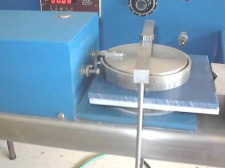
In order to measure wall friction properties, a Jenike Shear Tester -- the standard through ASTM in the U.S. -- is used. Consider, that friction develops between a solid and the walls of a bin or hopper as it interacts with the surface. This friction determines whether the solid will slide on the wall (mass flow) or adhere to the wall and preferentially slide on itself (funnel flow).
Photo 1 shows that the bottom "cell" of the shear cell (normally used for cohesive properties testing), arrangement has been replaced with a sample of wall material. The weight hanger applies the load simulating pressures acting in a bin and shear force is recorded as a function of this pressure. The information gathered during this test, results in a wall friction angle that is subsequently converted to a hopper slope for mass flow.
A major consideration is that there is no "magic" angle for mass flow. The following is a common statement: "all I have to do to develop mass flow is to design my hopper with an angle of 70°". What is wrong with this statement? Mass flow is dependent on wall friction properties and is affected by the smoothness and steepness of the hopper wall and the properties of the bulk material. If you design your hopper for 70°, it may achieve mass flow; but, it may flow in mass flow at a shallower angle say, 65° or may also require 85°. Wall friction testing is the only reliable way to determine the correct hopper angle for mass flow.
Dr. Andrew W. Jenike in his Bulletin No. 123, provides design charts that are used to convert wall friction angles to hopper angles for both conical and wedge shaped geometries. These charts are plots of wall friction angles vs. hopper angles. They are categorized by values of "effective angle of friction", (delta, δ), which are listed in 10° increments ranging from 30° to 70°. δ is a function of your material’s flowability and is easily obtained from flow properties tests. For each value of δ, there are combinations of wall friction angle, phi-prime, Φ' and hopper angle, theta, θc and θp (for conical hoppers and planar hoppers, wedge type, respectively).
These charts may be used in several ways. However, the common approach is as follows:
Photo 2, shows a typical conical hopper chart. Hopper angle and wall friction angle values are plotted on the X and Y axes, respectively. Notice that there is an uncertain region that lies between funnel flow and mass f low. The flow pattern within this region should theoretically be mass flow; however, slight differences in material properties or hopper angle due to fabrication, can result in funnel flow. A switch back and forth between mass flow and funnel flow can cause severe bin vibrations and other problems. This region represents a margin of safety to minimize the above effects.
Always remember, Jenike's charts give the hopper angles in degrees from vertical.
These charts can be used to determine if an existing hopper that is 20° from vertical and fabricated from carbon steel with a 15° Φ' will ensure mass flow. Using both values shows that the hopper will flow in mass flow; however, we all know what happens with carbon steel--it rusts! A rusted carbon steel surface may have a Φ' value of 30° now and that would force the hopper to flow in funnel flow.
A second, and more common way to use the charts is to use the Φ' value of 15° (from horizontal), you can determine the minimum hopper angle required to ensure flow along the walls (see Photo 3). The resulting hopper angle required for mass flow is determined by reading over to the outer edge of the uncertain region and then reading down to (in this case) about a 32° from vertical. In actuality, Jenike’s charts indicate the outer boundary line of the uncertain region and the user has to back off 4° on the hopper angle, as a safety factor. This makes the recommended hopper angle, θc (degrees from vertical), 28°.
Different design charts are used for wedge hoppers (refer to Photo 4). Notice that there is no uncertain region in this chart as on the conical hopper design chart, because there is no definite boundary line between mass flow and funnel flow in wedge-shaped hoppers. Thus, wedge shaped hoppers are more forgiving than a conical hoppers and can handle materials with a wide range of flowability. You read the chart the same as a conical hopper chart except that you do not have to allow for a safety factor.
Using the correct hopper angle for mass flow is critical to your design. If you decide to use a different solid in your bin, (even if it is the same material, but from a different vendor), you would be wise to check wall friction values to ensure the proper hopper angle.
Joseph Marinelli is a consulting engineer and president of Solids Handling Technologies, Fort Mill, SC. He has been providing testing and consulting services since 1972. As a former consultant with Jenike & Johanson Inc., he has years of experience testing powders and designing bins and feeders for reliable flow. He lectures frequently on the topic of powder handling, and has published several papers, including an article in a chemical encyclopedia and two in a food powder book. For more information, call 803-802-5527 or email [email protected].
You May Also Like


