

Sign up for the Powder & Bulk Solids Weekly newsletter.
Richard Denk
February 1, 2008
10 Min Read
.svg?width=850&auto=webp&quality=95&format=jpg&disable=upscale "Containment System Concepts for OEB1 through OEB5")
|
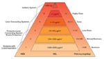
Figure 1: For OEB values 1 through 5, the toxicology of the pure substance is considered. The goal is to determine a plant classification by selecting appropriate production |
The production of active pharmaceutical ingredients (APIs) increasingly requires the implementation of directives such as Q7A from the International Conference on Harmonisation of Technical Requirements for Registration of Pharmaceuticals for Human Use (ICH). This requirement has become even more important since it was incorporated in the European Community Good Manufacturing Guide as Annex 18. Equally important, however, is the implementation of measures that improve safety in the production of intermediates and APIs. This article describes the type of facility that can be designed to handle and contain APIs with operator exposure limit/operator exposure band (OEL/OEB) levels 1 through 5.
Collective Safety Measures
The implementation of collective safety measures (closed systems) is stipulated in EU Guideline 89/391 EEC and in the new Act for Hazardous Goods (www.baua.de). Similar measures are codified in U.S. Occupational Safety and Health Administration regulations. For effective operator safety, it is paramount to enclose the product at the location where it is produced and to keep it enclosed from the first step of the process until final packaging. However, when the product is transferred to a different processing facility, or when it is placed in transportation receptacles such as containers, drums, sacks, or bulk bags, a critical situation can arise. If transport is unavoidable, the product is given an OEL/OEB classification to determine the materials’ workplace boundaries (allowable weight of material per cubic meter) and to enable the facility to select the appropriate transfer system.
|
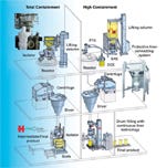
Figure 2: Diagram of a facility used for the contained handling of APIs |
For OEB values 1 through 5, the toxicology of the pure substance is considered (see Figure 1). The goal is to determine a plant classification by selecting appropriate production facilities and operating procedures for each respective product. An average concentration load for each API stated in micrograms per cubic meter, the OEL is calculated by giving workers respiratory examinations over an eight-hour period.
The term containment is used to describe the process of enclosing a biological agent (medically active substance, pathogenic factor) or other material within a defined space. In the pharmaceutical industry, total containment protects humans and the environment while preventing cross-contamination. Hecht Technology (Pfaffenhofen, Germany) has developed systems for all OEL/OEB levels, workplace boundaries, and major transportation receptacles.
Facility Design for the Production of Highly Hazardous APIs
|
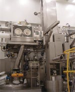
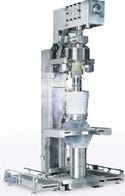
Figure 3: Isolator used for OEB 5 bulk bag discharge |
The diagram in Figure 2 illustrates a production facility that has two reactors, two centrifuges, and two dryers. The reactors are located on the third floor, while the centrifuges and dryers are on the second floor. The transfer of the solid starting material and the intermediates (at several production stages) takes place on the third floor. Because the production process involves extremely hazardous APIs, the transfer of solid material and final product filling are executed on the first floor using containment systems.
Bulk Bag Filling. The contained handling of APIs takes place in a Class D (or Class 100,000) cleanroom, which has a combined high-containment station for filling bulk bags (for intermediates that are discharged back into the reactor) and drums with liners (for APIs). Starting material 1 (processed in production area 1) is extremely hazardous and classified as OEB 5. It requires total containment. Consequently, its transfer must be executed using isolator technology. Starting materials 2 and 3 (production area 2) are toxic and classified as OEB 4. These materials require high containment. Their transfer requires the use of a powder transfer system (PTS), a drum and sack containment system, and a protective liner connecting system (SAS).
Especially in the containment business, the use of flexible disposable receptacles such as bulk bags is cost-effective. Bulk bags can deliver materials with workplace boundaries as small as 200 ng/m3. Apart from their low purchase price, bulk bags do not require cleaning—in contrast to containers. Moreover, the discharge performance of flexible receptacles offers important advantages over rigid receptacles.
|
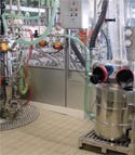
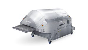
Figure 4: OEB 2–5 PTS/DCS vacuum conveyor system |
As shown in Figure 2, large amounts of material (25 kg or more) are discharged into the process from bulk bags, a process that takes place on the third floor. For this purpose, the bulk bag discharge stations are equipped with Hecht lifting columns to accommodate bags of different sizes and to lift them during discharging so that product can exit easily. In addition, the bulk bag discharge stations include an agitation unit in the form of a rocker with adjustable height. The rocker massages the bottom of the bulk bag and can even discharge most bridging products. The height of the agitation unit is adjustable, enabling the rocker to grasp the bottom of the bulk bag while it is stretching.
Using Isolator Technology for Bulk Bag Discharge. In production area 1, the product inlet system of the reactor is connected to an isolator, enabling the contained transfer of solid materials. Shown in Figure 3, the isolator has a front door that is equipped with integrated gloves. Push-push filters allow contamination-free filter exchange after the operation has been completed. A rapid-transfer port can be used to extract the parts located inside the isolator for cleaning purposes. In conjunction with a canister, the port can also be used to inject small quantities of material (up to 25 kg) into the process. After entering the isolator, the material is then discharged into the reactor.
The core of the bulk bag discharge station is a docking system that enables the bulk bag outlet to be connected to the isolator with two integrated in-liners. This technology, the first of its kind, allows facilities to discharge a bulk bag in a completely contained manner. A small workplace boundary of 200 ng/m3 is achievable.
|
Figure 5: Bulk bag discharge station with a Hecht protective liner connecting system |
Material Transfer Using a PTS Vacuum Conveyor System with the Containment Drum and Sack Emptying System. In production area 2, the product inlet system of the reactor is equipped with a PTS. This system forms the lock for the transfer of solid material into a pressurized vessel that contains a preloaded solvent. Under the same pressure as the reactor (6 bar), the PTS chamber extracts the oxygen from the powder and then discharges the contents into the reactor using nitrogen. The system improves safety in the reactor through oxygen-free transfer of solid materials.
The PTS is connected to two different transfer systems. Large quantities of material (50 kg and more) are inserted into the PTS via a bulk bag discharge station. Small quantities (up to 50 kg) are inserted using the containment drum and sack emptying station. Figure 4 shows the PTS/drum/sack emptying station.
To perform the insertion process, a drum with two in-liners is necessary. The outer in-liner is connected to the bottom of the containment system, while the inner in-liner, which is filled with product, is connected inside the containment system. Inserting material into the PTS is performed by an operator using two gloves that are integrated into the containment system. The product is evacuated from the drum by means of a capped suction lance, which is connected to the PTS. The drum and sack containment system achieves a workplace boundary of just 1 µg/m3. For cleaning purposes, both the PTS and the drum and sack containment system are equipped with clean-in-place units, which allow cleaning fluid to be emptied directly into the reactor.
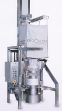
Protective Liner Connecting System (SAS). In production area 2, the core of the bulk bag discharge station is the Hecht-ProClean SAS, which makes it possible to discharge a standard bulk bag in a completely contained manner (see Figure 5). A liner depot with about 15 m of protective liner is centered on top of the product guide pipe, which is enveloped by the end of the protective liner. Before opening, the bulk bag in-liner makes a dust-tight connection to the protective liner using a disposable ring. The protective liner is then drawn back from the liner depot. Upon discharge, the operator tapes off the in-liner and protective liner above and below the disposable ring and then separates the liners in the middle of the tape. The product guide pipe is sealed again and the contaminated protective liner is discarded. This procedure ensures that product will not escape into the environment at any time. A small workplace boundary of 1 µg/m3 is achievable using this protective liner system. As a result, the system also qualifies for carcinogenic, mutagenic, and reprotoxic substance certification. In addition, the suction shoe on the connection to the PTS conveyer tube contains a lump breaker.
|
Figure 6: Filling product into drums with a continuous liner |
Automatic Reference Sampling. Reference samples for quality control can be obtained from the dryer located on the second floor of the facility. The sampling equipment guarantees product containment. A device integrated into the dryer obtains a sample from the dryer and places it into a collector, after which it is evacuated by a mini-powder-transport system. This operation places the reference sample in a glass vial. The transport system is located in a glove box in which the filled glass is undocked safely from the system and sealed. Then a rapid-transfer port is used to extract the sealed glass from the glove box. Like other facility components, the mini-powder-transport system has clean-in-place functionality.
Filling Intermediates into Bulk Bags Using Isolator Technology. The cleanroom in production area 1 has a total-containment station for filling bulk bags with intermediates. The bulk bag inlet is connected to an isolator. Floor scales control the product weight in the bulk bags. As is the case with bulk bag discharge, the core of the bulk bag filling system is the connecting adapter for the bulk bag inlet’s two in-liners. Thus, bulk bags have a small workplace boundary of 200 ng/m3.
Filling APIs into Drums Using a Continuous Liner. Production area 2 is equipped with a sieving machine, a metal deposition unit consisting of a permanent magnet, and an in-line metering system without moving parts that accurately fills the drums in the product-contact area. The metal deposition and metering systems rest on a lifting column. After cleaning has taken place, the lifting column can lower the systems to operating height to enable maintenance work. The core of the filling facility is a Hecht continuous liner filling head (shown in Figure 6), which performs contamination-free product filling. This special filling head accommodates a package that holds up to 80 m of liner. Having the liner centered above the product outlet ensures that the filling head is never open to the environment. An appropriate quantity of liner is pulled down to accommodate the size of the drum and is then filled with product. Once the liner bag has been filled, it is sealed twice using an integrated bag sealer. After both seals have been automatically separated, the operator closes the drum.
The drums are transported into the storage area on roller conveyors through a material lock. The material lock is equipped with air jets to clean the drum surfaces. The same system is used in the operator lock.
Conclusion
After a company has established OEL/OEB values for a new API or it has determined workplace boundaries for chemical products, it can define the technical task at hand with an eye toward minimizing investment and operating costs. In addition to being based on OEL/OEB values, a facility’s design concept is based on the different flow behaviors of the products it handles, which determine the company’s choice of suitable containment systems.
Richard Denk heads the pharmaceutical department at Hecht-Anlagenbau GmbH. He can be reached at [email protected]. Readers can visit Hecht Technology’s Web site at www.hecht.eu, and the Web site of the company’s U.S. representative, KMPT USA Inc. (Florence, KY), can be viewed at www.kmpt.net.
About the Author(s)
You May Also Like
Editor's Choice
.svg?width=800&auto=webp&quality=80&disable=upscale)