Sign up for the Powder & Bulk Solids Weekly newsletter.
November 30, 2017
10 Min Read

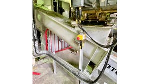
Figure 1: Solids don’t naturally form a uniform level, so there are often huge differences between peaks and troughs.
Measuring the level and volume of powders and bulk solids in a vessel can be considerably more challenging than determining the level of a liquid. While measuring liquid level presents many challenges, most present a uniform surface. Solids don’t behave as predictably, and this often causes measurement issues.
The most fundamental challenge when measuring the level and volume of solids is the uneven and shifting nature of the material surface (Figure 1). When determining liquid level, only a single point on the surface needs to be measured because the level at that one location will be the same as at any other point within the vessel. However, the same is not true of solids.
Few solids flow readily enough to spread evenly, and their tendency to clump, pile, and stick can change with atmospheric conditions. With filling and emptying cycles, a multitude of peaks and troughs can form, and constantly change as product is added and removed. Depending on how much the material can pile before sliding and the width of the vessel, the difference between the level of a peak and a trough can be as much as 100 percent. Additionally, the particles of the materials can vary from very fine powders to effectively large rocks. These characteristics make level measurement much more difficult than with liquids.
In this article, we’ll examine these level measurement challenges and look at ways to address them in different sized vessels using a variety of measurement techniques and technologies. Examining the strengths and weaknesses of each technology helps when choosing the best level measurement instruments for the application.
Traditional Measurement Approaches
The most basic measuring technique is sending a human operator to the top of a vessel to look inside. This normally involves opening a hatch or uncovering a nozzle. The operator may be equipped with a flashlight, tape measure, and perhaps a pole to knock down formations. This will give a general idea of how much is in the vessel. For some applications, this may be sufficient, but it isn’t very good for accuracy or repeatability, particularly when different operators perform the task.
There are also obvious potential safety concerns with someone climbing a vessel, and additional concerns with being exposed to the product. If the operator is opening the hatch after a recent product movement, he or she might be greeted with a blast of dust. If the product is benign, this might only be an annoyance, but for other products it could be irritating or even toxic.
Facilities wanting to move past the visual approach may use a mechanical solution such as a “yo-yo.” This device lowers a weighted bob onto the surface of the material. By measuring the length of wire required for the weight to touch the surface, the level of the material can be determined. The yo-yo action can be manually or automatically activated to provide readings at specific intervals. Manual systems of this type require an operator at the top of the tank. Since they are mechanical, they require regular maintenance, which means sending a technician to the top of the vessel even with an automated system, presenting safety concerns. There are also limitations in terms of accuracy, reliability, and repeatability of measurement. The yo-yo will report a reasonably accurate reading of the specific spot where the bob lands, but it cannot give any indication of the unevenness of the overall surface.
One problem observed is trying to take a reading during a filling cycle. If the yo-yo bob goes down while product is being added, it can become engulfed and buried by the product. If it is unable to pull free, it can jam the mechanism or break the wire. If the bob is left in the product, it may eventually be carried into the process where it could cause damage to equipment.
Toward More Precise Measurement
Level instrumentation providers have made much progress on more sophisticated automated systems for solids measurement. Consequently, many plant operators have chosen to upgrade to continuous automatic measurement technology—helping to improve safety, reliability, and repeatability, while enabling accurate and reliable continuous measurements—with data sent from remote locations to a control room.
The most common and successful technologies for solids measurement are non-contacting radar, guided-wave radar (GWR), and acoustic phased-array antennas. They all have their specific capabilities, advantages, and drawbacks, depending on the application. The common element of these technologies is the use of a time-of-flight approach. An acoustic or microwave pulse is transmitted from the top of the vessel, and distance is calculated by the time it takes the pulse to reach the surface and return. This is an oversimplification of what’s happening, but it provides a useful model of the concept.
Applications within this context can be divided into two main types. The first is continuous level measurement in smaller vessels used to control a production process or make sure that there is material available downstream. In such applications, quick changes in surface level can occur due to the speed at which material enters and exits the vessel. This requires technology capable of making very fast level measurements.
The second application type is volume measurement in larger vessels or warehouses used for bulk storage, which is often related to inventory control. In these applications, there is usually a much greater surface area to monitor, and inaccurate measurement can lead to a huge discrepancy in product volume. Here the surface level changes at a much slower rate, and therefore the speed of measurement is less important, but greater accuracy is required to support better inventory management. When selecting a measurement technology, it is important to understand whether volume or level is the desired primary measurement, as this will influence the technology choice.
Guided-Wave Radar
GWR level transmitters provide continuous level measurements based on microwave technology. Low-energy microwave pulses are guided down a probe. When the microwaves are reflected from the material surface back to the transmitter, the position of the surface can be measured. The distance corresponds to the spot on the surface where the probe contacts the material, so there is no compensation for uneven surface contours.
GWR level transmitters are especially well suited for smaller vessels with a diameter of less than 33 ft, that contain powders and small granular materials, and in installation areas where space is restricted. The higher the dielectric constant of the material the better as this provides a stronger reflection. When the material’s dielectric constant is low, only a portion of the electrical signal is reflected off the top of the material. The rest of the signal continues down the probe. Because some of the signal continues, GWR transmitters can use probe-end projection functionality to allow for measurements when the surface pulse is too weak to be detected (see sidebar). This commonly occurs when the material dielectric constant is very low, especially in combination with a long distance to the surface, and/or electromagnetic interference.
Because the probe extends down into the material, in solids applications it becomes embedded, somewhat like a tent stake. The weight of the material on the probe causes down-pull forces on the probe, the transmitter and vessel roof. This tensile force depends on silo size, material density and the friction coefficient and should be calculated to ensure all the elements are strong enough to withstand it.
Non-Contacting Radar
Non-contacting radar level transmitters also provide continuous level measurements, but there is no contact with the material surface. Pulse radar or frequency-modulated continuous wave (FMCW) techniques are used to perform the measurement. With pulse radar, microwave pulses are emitted towards the material and reflected to the sensor, with the level being directly proportional to the time taken between the microwave signal being transmitted and received.
With FMCW (Figure 2), a continuous signal sweep with a constantly changing frequency is transmitted. The frequency of the reflected signal is compared with the frequency of the signal transmitted at that moment. The difference between these frequencies is proportional to the distance from the radar to the surface, which enables the level to be measured. FMCW devices can improve the measurement of solids compared to pulse transmitters because they continuously send out microwave energy, meaning that FMCW transmitters are much better than pulse devices at determining weak echoes within a noisy environment. Even still, inclining or sloping surfaces deflect energy away from the radar and can generate several small reflections. By using special measurement algorithm that merges the peaks of an uneven surface, a non-contacting radar level transmitter can provide accurate measurements, even with very fast changes in level.
Non-contacting radar devices still see only the portion of surface within their beam angle. Like GWR, this makes them a suitable choice for applications using smaller vessels or silos, where fast movements are possible but accurate volume measurements are seldom needed. Unlike GWR, there are no restrictions with respect to the weight of the material and pull forces. Due to recent improvements, FMCW technology requires less electrical energy allowing users to benefit from the superior accuracy and sensitivity without needing to install additional cabling infrastructure when making upgrades from other types of two-wire instruments.
Acoustic
Some level transmitters offer a configuration similar to non-contact radar, but use acoustic frequencies rather than microwave. These have their advantages particularly in dusty environments.
Additionally, acoustic transmitters using phased-array antennas can perform sophisticated scans of the product surface in a vessel (Figure 3). After sending signals at three different frequencies, the antennas receive multiple echo signals from the walls and contents. Using these integral antennas, the scanners continuously measure the direction and distance of each echoed signal and generate a coordinate of the echo inside the vessel. Digital signal processing within the instrument samples and analyzes the echoed signals, and produces accurate measurements of the level and volume across the entire surface within the much wider beam angle of the device.
Matching the received data with known vessel dimensions allows the instrument to calculate product volume, providing continuously accurate inventory values. This enables efficient inventory management and allows companies to have the right amount of stock in the right place at the right time, and ensures that capital is not tied up unnecessarily.
Matching the Technology to the Application
The challenges of measuring the level of solids in a vessel may appear daunting, but are largely solvable using the range of technologies available today. The needs of the process and the plant or facility will determine how sophisticated and precise the approach needs to be for a given application. Fortunately, the choices available can deliver the data and information needed to help keep a plant and process running smoothly and profitably.
More Than One Way to Solve an Application
The reflectiveness of a product to the microwave frequencies used with radar transmitters depends on its dielectric constant (DK). As the DK increases, so does the signal. But some products have a very low DK and therefore become effectively invisible. As a case in point, an injection molder making parts from acrylonitrile butadiene styrene (ABS) resin pellets found that the DK was typically around 2.0, which is borderline for getting a good signal back when using a Rosemount 5300 Level Transmitter. When the primary reflected signal was too weak to be usable, the transmitter had its own backup plan.
Since the signal sent down the probe simply continues traveling down until it reaches the end of the probe, the transmitter uses the signal to its advantage. The end of the probe kicks back a strong reflection which the transmitter can easily read. Naturally the length of the probe is known, so how did this help?
The microwave signal moves more slowly when travelling through the pellets than it does in air, so it takes longer for the for the signal to return than if the probe is simply hanging in free space. Using the known length of the probe and the DK of the pellets, the transmitter is able to calculate how much ABS the pulse has traveled through based on the delay to its normal return time.
This capability allows the GWR transmitter to operate in either mode as necessary based on what kind of reflection it is receiving. This approach is recommended for solids with a dielectric constant less than or equal to 2.0, for example lime and various polymers, such as polypropylene, polyvinylidene difluoride (PVDF), polyethylene, ABS, and many others.
Lydia Miller is senior marketing engineer, Rosemount Level, Emerson Automation Solutions. For more information, visit www.emerson.com/en-us.
For related articles, news, and equipment reviews, visit our Instrumentation & Control Equipment Zone
Click here for a List of Instrumentation & Control Equipment Manufacturers
Get information on the 2018 Powder & Bulk Solids Conference & Exhibition
You May Also Like
Editor's Choice


.svg?width=800&auto=webp&quality=80&disable=upscale)