Sign up for the Powder & Bulk Solids Weekly newsletter.
October 18, 2016
9 Min Read

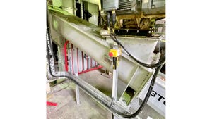
Figure 1: Circular clinker silos used to store cement, concrete, and similar materials pose problems for traditional level measurement instruments.
Cement companies typically use free space radar measurement instruments to monitor the level of materials used for the manufacturing of cement, concrete, and other building materials. Free space radar level instruments have proved themselves over the years as a way to overcome measurement problems in circular clinker silos (Figure 1), bunkers, slim silos, stockpiles, mechanical conveyor systems, and crushers.
(see Figure 1)
Newer free space radar level instruments are better able to deal with problems such as dust, abrasion and high temperatures by utilizing new developments in signal processing and other areas.
Level Measurement Issues
Silos holding solid materials have several measurement issues other than dust and high temperatures. The silos may have obstructions such as feeders, agitators, and heating elements that can interfere with a level measurement. Flow out of the silo can be impeded by the formation of stagnant arches, ratholes, and zones caused by “hammering” at a hopper wall and “funnel flow.”
Ultrasonic level instruments can lose the measurement during filling when large amounts of dust are produced, while electromechanical systems—which lower a weight to the top of the pile—risk the weight being buried. Electromechanical systems also suffer wear from the abrasive media. With any mechanical system that has moving parts there is a higher or more frequent level of maintenance required.
Problems may also arise with level measurement in narrow compartments with different grain sizes. High noise levels during filling can affect the measurement, especially with ultrasonic instruments. With electromagnetic instruments, the high noise generates vibrations that can make the measured signal be erratic and not reliable.
With mechanical conveyor systems, monitoring the belt load or feed points into or out of the silo is difficult for electromechanical level instruments because the material is moving and the level can change rapidly. Fast response times are often required, and electromechanical instruments are slow to respond.
Indoor or outdoor stockpiles are used to hold incoming material or outgoing final product a varying angle of repose in the surface of the media can create challenges for non-contact and traditional level instruments. The level instrument may have to be mounted on a support above the storage pile, making installation and maintenance difficult. An alignment device or adjustable mounting bracket on the device is often needed to adjust the radar to the angle of repose of the material to as close to perpendicular as possible. Setting the proper angle of repose with a radar transmitter will improve reliability and accuracy of the application.
Free space radar level instruments overcome all these problems.
Radar to the Rescue
Free space radar level instruments (Figure 2) are typically used in clinker silos, and new developments in radar signal processing are making radar more effective than ever.
(see Figure 2)
Two main areas of improvement over the recent years with radar technology bring about improved reliability and accuracy. One is the new “intelligence” in the electronics that aids in overcoming uneven levels in silos and conveyors. The second is higher frequency from 6 to 26 GHz, allowing for tighter beam angles that improve reliability by not getting reflections from obstructions in the silo and other uneven levels. The beam is the signal sent to and reflected from the material in the silo. This allows level measurements in narrow compartments and improves reliability even with different grain sizes.
A 4-in. antenna results in improved focusing of radar waves with a beam angle of only 8°, and high signal dynamics. With these properties, a modern radar instrument (Figure 3) is able to accurately measure level in circular compartment silos during filling.
(see Figure 3)
Beam angle is important because it determines how close the free space radar can be installed to the wall of a narrow compartment. The beam should never reach the wall because it could interfere with the radar signal. For example, when a free space radar instrument horn with a wide beam angle is installed too close to the side wall, this can cause non-linear inaccuracies throughout the measurement range.
A wide beam angle has its advantages. For example, a 6 GHz radar instrument has a lower, broader frequency than a 26 GHz instrument, so it's better at penetrating dust. Wide beam angles also provide more of an average representation of the surface. To maximize reliability of a measurement, the installation of the transmitter should be from 1/2 to 1/3 the radius of the vessel.
Advanced Algorithms
With traditional time-of-flight measurements used by radar and some other level instruments, a pulse is emitted, reflected by the surface of the medium, and received by the radar instrument’s antenna. The level in the silo is calculated based on the time it takes for the signal to return. The calculation also makes use of the echo signal curve built into most modern radar level instruments.
Obstacles in the radar beam path, other instruments for example, may generate an interfering echo signal. These obstacles are traditionally excluded from the echo signal analysis based on a mapping function; that is, only signals over the mapping curve are accepted as valid level signals. If the level signal goes below the mapping curve when filling or discharging a tank, incorrect analyses may occur. The signal jumps erroneously, for example, to a so-called double echo which follows the echo at twice its distance. After the level passes the obstacle, the echo jumps back to the correct level signal.
Advanced signal analysis algorithms, such as multi-echo tracking (Figure 4), provide a more intelligent and reliable echo signal analysis. When the level instrument is first commissioned, a static map is generated by the operator. This can be done with an empty vessel or with product in the vessel. The static map then runs in the background while multi-echo tracking processes the resulting signal.
(see Figure 4)
With multi-echo tracking, all echo signals—new and old—are mapped. If obstacles protrude into the signal path, they generate a corresponding signal. The analysis tracks the level signal even if it ranges below the static map. The level transmitter performs this function during every scan, guaranteeing safe and precise measurement even in the presence of new obstacles in the tank. The ability of the transmitter to learn and evaluate each critical change brings an increased level of confidence to the process measurement.
The self-learning software algorithms are capable of monitoring and characterizing up to 20 microwave reflections simultaneously, including:
* Level signals
* Interfering signals
* Doppler signals
* Ground signals
The signal type is defined by evaluation of the various reflection properties such as height, position, speed, and direction of travel. These evaluation algorithms make it possible to reliably evaluate a signal reflection generated from the level even when it is beneath the mapped interference.
Dealing with Dust
In dusty environments it is common for buildup to form on the radar emitter located inside the horn and weaken the propagation of the signal transmission. The emitter transmits the radar signal and can get an accumulation of dust buildup over time, interfering with the strength of the signal. A risk of strong buildup formation is possible in silos and bunkers, and the use of purge air attached to the horn (Figure 5) may be necessary.
(see Figure 5)
A loss of echo or false high signal can occur at the “Near Field” of the instrument; that is, the area near the process connection where the emitter is located. With the advanced diagnostics function in a modern radar level instrument, this problem can be addressed. An evaluation is done at the time of installation to determine the area of the incoupling to provide the baseline for a clean level measurement. The area under the envelope signal close to the process connection is called “the area of incoupling.” The diagnostic block compares the value for the area of incoupling to the area established in the baseline. This area will decrease as build-up occurs on the radar emitter and an alarm can generated before the transmitter has a loss of signal or fails.
The output from the advanced diagnostics can be used to schedule preventative maintenance or activate an air purge to blow off the build-up. The output of the device can either be an open collector or a 4-20mA signal. The air purge can be run as a predictive measurement, while a call for preventive maintenance eliminates excessive build-up around the horn area before the failure of the device.
The radar instrument itself can monitor other values as well, check against the allowable values, and provide an alarm before the instrument fails or loses its signal.
Advanced diagnostics can also monitor various inputs:
* Linearized level (for irregular shaped vessels and strapping tables)
* Unfiltered distance (for fast changing processes to react without any algorithm dampening)
* Relative echo amplitude (to monitor the signal strength in relation to the measured level)
* Electronic temperature (to monitor the temperature influence)
* Terminal voltage (to check the quality of the wiring online for water ingress or corrosion)
Easier Replacement
Digital technology employed in most modern radar instruments makes replacement of an instrument easier. For example, the Endress+Hauser FMR57’s display (Figure 6) stores instrument data so the display can serve as a data carrier, similar to a USB stick. In this way, the complete configuration settings can be easily transferred from one instrument to the next or restore the configuration data back to the instrument.
(see Figure 6)
When a level instrument needs to be removed for maintenance, the display is simply connected to the next instrument. Activating the “duplicate” function transfers the parameter settings directly to the next instrument. This feature reduces the time required for commissioning new instruments.
Summary
Measuring level of cement, concrete, and similar materials in silos has always been a problem for traditional level instruments such as ultrasonic and electromechanical devices. Free Space Radar level instruments have been widely used in the cement and bulk solids industries for many years, with great success. Recent developments in signal processing algorithms are making radar level instruments more accurate and reliable.
Dean Mallon is a national marketing manager for the level products at Endress+Hauser. He remains involved in various committees and is currently serves on the API 2350 5th edition working group. For more information, visit www.us.endress.com.
For related articles, news, and equipment reviews, visit our Instrumentation & Control Equipment Zone
Click here for a List of Instrumentation & Control Equipment Manufacturers
You May Also Like
Editor's Choice


.svg?width=800&auto=webp&quality=80&disable=upscale)