July 27, 2017

Feeding ingredients into a continuous process using a loss in weight feeder requires refilling the integral feeder hopper to maintain a continuous feed. The sizing and refill of this hopper are an integral part of the overall loss in weight feeder system design.
Flow of ingredients into the process is to be continuously steady at a required feed rate set point. However, the feeder undergoes disturbances while achieving an accurate set point with steady reliable feed flow.
Measuring the flow rate of dry particulate ingredients differs from liquids in one critical characteristic its density. Specific gravity (density) for liquids is a constant parameter under stable temperature conditions. In dry particulate ingredients, the bulk density (density) is not a stable parameter. Bulk density is the term defining weight per volume. It can vary by several percent mainly based on varying air entrainment. For example, the bulk density of flour can vary from 30 to 40 lb/cu ft, depending on its transfer to the feeder and its level in the feeder hopper. Also, the bulk density can vary in the feed screw of a dry ingredient feeder. As a result, the output from a feeder must be weighed constantly with a fast correction of screw speed to maintain an accurate feed rate at set point.
A continuous loss-in-weight feeder has a control system (scale and controller) that can make a series of fast weight measurements and make corrections to the screw speed to control the feed rate at set point within close tolerances, typically better than +/- 1% of actual feed rate.
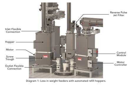
To measure the weight of ingredient being fed, the entire feeder (screw feeder, drive, screw trough, agitation, hopper and ingredient in the hopper and screw trough) is weighed. The highest weight measurement accuracy occurs when this feeder and stored ingredient are as "light" as possible.
In Diagram 1, the loss in weight feeder and automated refill hopper is shown and components are identified. (see Diagram 1)
The screw feeder model is selected to be an appropriate size to feed the ingredient at the maximum and minimum required feed rates. This could require using one or more screw sizes (diameter/pitch) in the feeder to achieve the feed rate range.
The integral feeder hopper is sized to accommodate the selected feeder and be of "sufficient" volume to ensure a reliable and accurate feed rate. There is a commonly used "rule of thumb" to select the size (volume) of the feeder hopper.
Feeder Hopper Volume=max feed rate÷min bulk denisty×(1/15)×0.6
mass feed rate - lb/hr
min bulk density - lb/cu ft
1/15 - represents 15 refills/hr
0.6 - this allows for 20% heel in the hopper at start of refill (plus the volume of screw trough) and 20% freeboard (hopper not filled completely)
Typical Calculation
Feeder Hopper Volume = 240 lb/hr ÷ 20 lb/cu ft × 1/15(hr) ÷ 0.6
= 1.33 cu ft.
(see Diagram 2)
In diagram 2, a graph is presented to show the continuous feed rate and the weight variation in the feeder as the ingredient is fed out. After four minutes of continuous feed out of the feeder, the ingredient in the hopper is at its refill weight and the refill valve on the refill hopper is opened to refill the feeder within 10 seconds. This feed out and refill cycle is repeated.
During refill, a continuous feed rate is maintained from the feeder. The feeder controller maintains the screw speed during the weight control portion of the feeding cycle. As the level of ingredient decreases in the feeder hopper, the bulk density in the feed screw may decrease causing the screw speed to increase. The feeder controller will quickly adjust the screw speed during refill to compensate and not over feed when the refill is completed.
The ingredient rate into the feeder during refill needs to be determined to ensure that the automated refill can be achieved in 10 seconds. During refill, dusty air is exhausted through the vent on the feeder hopper.
In our example, the refill volume is 60% of 1.33 cu ft and occurs in 10 seconds. The refill rate is calculated as follows:
Refill Rate = 1.33 (cu ft) ×0.6 ×60 (sec/min) ÷ 10 (sec)
= 4.8 cfm (this is the same rate of dusty air to be vented during refill)
(see Diagram 3)
The vent on the feeder hopper is required to exhaust dusty air during refill and allow atmospheric air to enter during feeding. If the ingredient is a powder or a granule (with fines) the dust collection during refill may need to be something better than a dust sock on the top of the hopper.
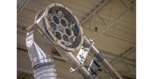
In diagram 3, a popular method of providing reliable dust collection during refill is a reverse pulse jet filter. The filter is back washed with a blast of air at the end of the refill to clean the filter so it is ready for the next refill. This filter also allows make up air to come in as the ingredient is fed out of the hopper. This type of dust filter returns the ingredient dust to the feeder hopper so that very little ingredient is lost.
In diagram 1, flexible connections are shown on the refill inlet and on the feeder outlet. A loss in weight feeder is sealed. It is supplied with specially designed flexible connections to provide a dust seal at the interconnection locations (inlet and outlet). These flexible connections are designed by the feeder manufacturer to ensure they do not affect the integrity of the weighing. During refill, the weigh hopper is slightly pressurized for a few seconds. The flex connection will expand (inflate). The vent (and dust collector) must release this pressure when refill is completed.
Refilling the Feeder for Loss-in-Weight Batching Applications
Loss-in-weight batching requires that the feeder is not feeding during refill. The feeder hopper should be sized to contain one batch. There should be enough time to refill the hopper after a batch is complete and before a new batch is started. If this is not possible, the batching must be interrupted (stopped) to allow the feeder hopper to be refilled. Loss in weight batching is a very accurate batching method. It may be possible to feed directly from the feeder into the production process.
Additional Comments:
1. The feeder hopper sizing calculation (rule of thumb) allowed for a four-minute feeding cycle under weight control between refills at maximum feed rate. At lower feed rates the time between refills is longer.
2. The refill cycle is longer than the time to refill the hopper. After refill is complete, 1-3 seconds is required for the ingredient to settle in the feeder hopper. The controller senses stable conditions and initiates weight control of feed rate automatically after stability occurs.
3. The upstream refill hopper only needs to store one feeder refill. However, it must be ready to supply one complete feeder refill before the next refill is initiated.
4. If the plant has its own dust collection system, it can be used provided the vacuum is removed from the vent during weight feeding. Also, the vent must allow for make-up air into the feeder under normal feeding operation.
5. Manual refill is possible. However, it is probably not practical if the time between refills is too short. If a manual bag dump station is to be used directly into the feeder, advise the feeder manufacturer to ensure this is designed correctly for ease of use and dust extraction.
6. Calculation examples in this article are simplified to help explain the requirement. For example, during refill, the feeder is discharging ingredient as refill is occurring. The increased weight of ingredient during refill was not considered in the refill time.
7. If inert gas blanketing is required, discuss this with the feeder manufacturer. Atmospheric pressure inside the feeder needs to be maintained.
8. There is flexibility in the controller to adjust the start refill and stop refill weights. Also, screw speed adjustments during refill can be programmed differently.
Conclusions
Loss-in-weight feeders are chosen to feed dry particulate ingredients reliably, repeatably (accurately), and dust free. An understanding of their sizing and operation during weighed feeding and refill periods will greatly help the feeder achieve its objectives. Too much storage in the feeder often results in poor reliability and repeatability. We recommend that extra storage is better provided externally.
Guy Catton P.E. is president of Brabender Technologie Inc. and holds a B.Eng. from the Technical University of Nova Scotia. He has over 30 years of bulk material handling and process experience. For more information, visit www.brabender-technologie.com.
For related articles, news, and equipment reviews, visit our Feeders Equipment Zone
Click here for a List of Feeder Manufacturers
You May Also Like


