Sign up for the Powder & Bulk Solids Weekly newsletter.
July 18, 2018
9 Min Read

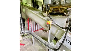
Low rate feeder with integral vibrated hopper and trough
Over the last 100 years or so, the problems of feeding and handling dry materials have been studied at great length and following intense and wide ranging R&D, industry now offers a broad range of solutions. Thumbing through the pages of Powder & Bulk Solids, those in search of an answer to their bulk solids feeding problems can find a variety of field-proven devices each with its own reported advantages.
There are some things common to every good feeder and those in the market for something accurate and reliable should know these basics and may then feel confident that what they are buying will get the job done.
But first, why is moving and metering dry solids so challenging? Let’s stop and consider that every manufactured thing around us from furniture to potato chips has either a liquid or solid component and in most cases both. In fact, about half of the raw materials used in the process industries are solids and the rest largely liquid with a small portion gas. We’re all familiar with handling liquids. Liquids are easily stored, can be moved by gravity alone, and can be accurately metered into process by pumps and valves. We look at the municipal water tower looming over the town and are confident that it will empty on demand. We meter the flow into our sinks with a simple faucet.
Whereas the problems of solids flow and metering have been resolved over the last century, liquids handling has been well understood for thousands of years. By the third century AD the city of Rome was being supplied with 300 million gallons of water per day (40 million cubic feet) carried through an aqueduct system by gravity alone. While a civil engineering marvel, conceptually the system was simple and accurate metering of that massive flow was accomplished through a series of mostly carved stone valves.
But if the challenge been to deliver 40 million cubic feet of flour a day and accurately meter it to the one million people of Rome, the task may well have overwhelmed the remarkable talents of some of history’s greatest engineers.
Contributing Factors
Let’s look at some of the things contributing to the solids handling and feeding problem. First there is the great variety of dry bulk products and this number has grown from those occurring in nature to thousands of new and unique materials created by industry. Plastic pellets handle differently from pigments, and wood shaving are vastly different from either. Then, for any given material, handling characteristics often change with moisture content, temperature, particle size, and the process environment itself. Most solids do not flow by gravity alone and require more than a simple valve to regulate feed rate.
Classifications
Fortunately, years of lab testing and thousands of industrial installations by dozens of manufacturers enable us to sort most of the great variety of dry bulk solids into four classifications based on handling and feeding characteristics. So, with some confidence we can narrow the scope of the problem into a relative handful of comprehensible variables.
Class I materials are generally granular and free flowing. Dry granular salt, dry whole grains, dry granular sugar and plastic pellets are examples of these kind of materials. Of all of the dry solids these are the easiest to handle, sometimes with near liquid ease. The simplest feeder will work well.
Class II materials are typically sluggish powders, 100-300 mesh, mildly cohesive and adhesive, and generally require some mechanical assistance to get them to flow and accurately feed. Examples are flour and starch.
Class III materials are the most challenging powders. They may be fine and adhesive (-325 mesh) and may alternately pack, bridge, and stick in a bin or feeder, and at other times flush uncontrollably through the system. TiOz, prepared foundry sand, and pigments are always adhesive, while hydrated lime cement, talc, and confectioners’ sugar may either stubbornly resist flow or fluidize to the point of loss of control. A critical consideration in feeding these materials is the proper design of the hopper or bin above the feed screw. The feed screw itself will normally be fully flighted as opposed to an open helix and, in fact, may be double flighted. If the feed screw is to extend beyond 18 in., an increasing pitch may be required to avoid binding in the feed tube.
Class IV materials present some of the most difficult and disparate feeding problems. These are often light density flakes, chips, shavings, and things like plastic scrap and chopped fiberglass. There are also metal turnings shredded tires and wire scraps. Given the variety, lab testing is usually a good idea and the ultimate feeding solution will often be heavily customized. The material will require mechanical agitation or vibration and if a screw feeder is used, an open helix design and generous clearances around the feed screw will be needed. The feed screw should be at least three times the diameter of the largest particle
So, if using these four classifications enables us to simplify the selection of a feed system, what are the common elements in any feeder that make it reliable and accurate?
Common Elements
Feeders come in a variety of types and configurations. Rotary feeders, belt feeders, vibrating pan feeders, and screw feeders are the most widely used. Each type must address the same basics. For illustration purposes let’s talk about screw feeders, perhaps the most common of the lot, and we will look at volumetric feeding as the primary building block of all accurate feeding systems.
In the last few decades scale and control technology has brought incredible accuracy and utility to feeding systems. Weight belt feeders, continuous loss-in-weight feeders, and batch feeders have never been more accurate and efficient. But no level of scale and control sophistication will fully compensate for the poorly designed volumetric feeder that is the platform on which everything else is built. If you can’t get reliable flow to and through the feeder, there’s nothing an accurate scale and state of the art control can do for you.
The elements of a good feeding system are: 1. Adequate on demand supply of material of a relatively uniform density to the feeder; 2. The complete filling of a volume (screw flight) with a uniformly dense material; 3. Striking off the excess material from the screw flight as material enters the feed tube; 4. Completely emptying the material from each flight; 5. Repeating this process at a steady rate. The whole operation can be seen symbolically in the graphic showing the repeated filling and emptying of a cup.
The supply of material to the feeder plays a critical role. It has to be adequate for the feed rate required, it must be dependably fill the feed chamber (trough), it must reduce the material to a uniform density, and it must fully fill each flight of the screw. Smaller feeders with integral hoppers handling Class II, III, and IV materials invariably require mechanical agitation or vibration, or both to handle this supply task.
For larger feed systems using independently mounted bins or hoppers, care should be taken in the design of hopper so that it flows on demand and delivers a uniformly dense product to the feeder. There are many instances where a perfectly good feeder is blamed for poor accuracy or erratic feed when the problem is poor or unreliable flow from the bin above. The supply bin must always be considered a critical component of any feeding system.
If the material is a Class III material with a tendency to readily fluidize, then other considerations come into play. In a feed system with a larger hopper, perhaps pneumatically filled, it is good practice to maintain a 20-30-minute supply of material in the bin at all times to allow entrained air to settle out. In this case, the bin flow aid should probably not be one that introduces air, but rather one that relies on vibration, mechanical agitation, or bin geometry. A properly designed vibrating bin bottom is an ideal solution since it encourages flow while deaerating the material before discharging it into the feeder trough. Often the feed screw for a Class III material will be a fully flighted screw or even double flighted to discourage material from flushing through the system. For those Class III materials that are highly adhesive, the pitch of the screw may need to be increased towards the end of the feed screw.
In any feeding application involving flow-resistant materials (Class II, III, & IV), matching hopper capacity and design to feed rate and refill method become critical considerations. Generally speaking low rates, below 10 cu ft/hr or say a 2-in. feed screw, can be handled with an integral hopper. These are supplied from the manufacturer with mechanical agitation and/or vibration to ensure uniform densification of the material, complete filling of the screw flights, and complete emptying of the screw flights on discharge.
At the other end of the spectrum with a feed rate of 1000 cu ft/hr (8-in. feed screw) the “hopper” may be a primary storage bin with a capacity of several thousand cubic feet. The basic concerns here are the same except the bin presents its own concerns and principal among them is that it must flow on demand and as much as possible prevent segregation of particle size as it empties.
In a large TiOz feed system, the singular challenge is adhesion and cohesion and the tendency of material to bridge in the bin or pack at the bin outlet where it mates with the feeder.
In a large hydrated lime system there is both the problem of compaction and bridging along with the likelihood of over aeration and thus flushing through the system.
In both cases the interface between the primary storage bin and feeder itself is critical. While it may be acceptable to go directly from a 3000 cu ft primary storage bin with a proper flow aid to an 8-in. screw feeder, it may not be advisable to directly connect the primary storage silo to the feeder where the feed rate is perhaps 150 cu ft/hr. In these instances, an intermediate hopper with appropriate flow aid should be installed between the primary silo and the feeder itself.
Other Considerations
Other considerations in selecting a feed system are climate, condensation in the bin, freezing, excessive heat, bin venting, and cleanability. One of the good things to emerge in the bulk solids handling industry in recent decades, certainly from the user’s standpoint, is the great number of reliable commercially available solutions to all these problems. The best equipment manufacturers will be able to demonstrate their capabilities in their labs and will be able to point to many successful installations where users will gladly share their experience.
Once the basics of a good feeding and supply system are laid out the design can be readily adapted to weigh feeding or batching and to virtually any requirement for process automation.
A solidly designed volumetric feed system may well survive several control upgrades over its service life. Attention to a few basics at initial selection will ensure dependable accuracy and stable process supply.
Gene Wahl Sr. is president, Vibra Screw Inc., Totowa, NJ. For more information, call 973-256-7410 or visit www.vibrascrew.com.
For related articles, news, and equipment reviews, visit our Feeders Equipment Zone
Click here for a List of Feeder Manufacturers
You May Also Like
Editor's Choice

.svg?width=800&auto=webp&quality=80&disable=upscale)