Sign up for the Powder & Bulk Solids Weekly newsletter.
March 19, 2020
12 Min Read

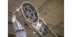
Figure 1: Slotted Hood CFD
There is a massive shift around the world to make projects not only cost effective in capital expenditure budgets, but also in operational and maintenance budgets for years to come. Whether it is for increased margins or to market the green and eco-friendliness of one’s products, energy efficiency is a big deal these days.
In the dust collection applications, we see this in the form of specifications for premium efficiency motors with variable frequency drives, filter cleaning methods to reduce compressed air consumption, and filter performance requirements--all of which are valid. Unfortunately, those are only talking about a portion of a ventilation system. A major component of a ventilation system that rarely gets looked at for energy savings is the ductwork. The ductwork can arguably be the most critical component in a properly designed dust collection system.
I have been a part of countless dust collection projects around the world from design, sales, installation, commissioning, and troubleshooting. In those experiences I have seen much effort go into the dust collector and filter selection, but the ductwork is rarely talked about other than materials, thickness, connection type, access, and any interferences with other equipment. I have seen the lack of attention to the ductwork go as far as customers leaving the design in the scope of the installation contractors, like it’s just another conduit or compressed air line in the plant. The problem with this lack of design attention is for the life of the system, you risk significant increases in energy costs and increased downtime due to ducting issues if you don’t follow fundamental concepts of ductwork design.
Free Webinar: Combustible Dust Testing Schema Offers Data for DHAs
There are a couple of ways that ductwork and hoods can be a massive energy savings for a dust collection system. These include hood designs that perform the required capture/containment of dust with less air, properly sized ducts to minimize static pressure requirements (while preventing dust fallout), and duct layouts to efficiently move air from the pickup points to the dust collector. I will discuss each of these in detail so that you can see the nuances that can reap energy savings for the next 20+ years of your system while delivering the continuous and reliable performance needed in a dust collection system.
Hoods
Dust collection hoods can be designed for two completely different ventilation methodologies: either collection or containment. It is critical that you properly identify the correct method for the application as it will lead to vastly different hood designs. If a hood is put into the wrong application there can be unnecessary static pressure loss in the system or an increase in air volume needs to achieve the desired dust collection performance, both of which increase energy consumption.
The collection methodology is where we want to pull every fugitive dust particle escaping the process to the hood before it is released into the surroundings. This leads to the hood needing to be designed to develop higher capture velocities at a certain distance away from the face of the hood. The typical hoods that are used in these situations are slotted, small pyramidal/conical, or large pyramidal hoods with multiple slots. Some typical applications for collection include:
* Drum loading
* Welding stations
* Open tanks with vapors
* Bag loading stations
* Belt cleaning systems
See Figure 1: Slotted Hood CFD
The containment methodology on the other hand is where we want to develop a negative pressure inside of the process to prevent dust from escaping the process equipment. This leads to the hood needing to be designed to have lower face velocities to minimize excess dust/product being pulled into the system while still creating negative pressure inside the equipment. This negative pressure causes any leakage points in the equipment to leak inward as opposed to puffing dust out. The typical hoods that are used in these situations are large pyramidal/conical hoods. Typical applications for containment include:
* Bins/silos
* Bucket elevators
* Belt enclosures
* Screw conveyors
* Screeners
* Packaging enclosures
See Figure 2: Pyramidal hood CFD
When a collection hood (slotted for example) is put into an application where a containment hood is required results in generating unnecessarily high face velocities at the hood. These high velocities create static pressure loss through the hood by an orifice affect. Worst case scenario is the hood is the governing pickup point for the ventilation system, meaning it determines the pressure requirement of the entire system. Then this excess static pressure generated in the hood causes the entire system static pressure requirement to be higher. This causes the fan to move to the left on its fan curve and decrease the air flow of the system. To recover that loss in air volume the fan will be sped up, which increases the amp draw by the motor and results in the use of more energy to move the same amount of air that was originally intended. Best case scenario is the hood is not the governing pick up point and requires a simple blast gate/damper adjustment as part of a complete system rebalance.
In a situation when a containment hood (large pyramidal for example) is put into an application where collection is required there are lower face velocities at the hood. This lower velocity causes capture velocities to decrease significantly and the dust to not be captured. This also tends to increase the air flow to the hood by opening the blast gate/damper. With this increased air flow at this point there is a decrease in air flow to the remaining points in the system. This creates a need to generate a higher total system air flow to maintain the other pick-up point performances. When the fan is sped up to create the higher total system air flow requirement not only does the fan have to use more energy to move more air but the total pressure requirement of the system goes up due to increased frictional losses with higher velocities in the duct work. This only compounds the energy losses of the system to generate the same dust collection performance.
Duct Sizing
When we size ductwork there is a balancing act to ensure it will perform adequately. It must be sized small enough to keep the dust entrained in the air stream throughout the system with sufficient convey velocities and to keep material costs down on the ducting. The other side of this balancing act is making the duct as large as possible to minimize both velocity pressures and static pressure requirements on the system which results in reduced fan size and energy costs.
When sizing ductwork for dust collection systems there are good guidelines in the ACGIH Industrial Ventilation Manual to help determine velocities to keep the dust entrained in the air flow all the way to the collector, but these are rules of thumb and not a complete list. If you truly want to optimize velocities and maximize energy savings, you need to get a sample of dust tested to determine the vertical and horizontal convey velocities specific to your dust’s properties.
If we lean too far to a duct system that is larger in diameter than needed, the dust will tend to fallout into the bottom of ductwork and cause dust buildup. The buildup will start to decrease the cross sectional area of the duct as the buildup increases. This decrease in cross section area results in the increase of air velocity in the duct and hence higher velocity pressure requirements. If this fallout occurs anywhere along the governing branch’s path the total system static pressure will increase as the velocity pressures increase. The increase in static pressure will cause the fan to move to the left on its curve, which results in lower volumes. This can cause a cascading effect of dust build up resulting in higher pressure followed by lower volumes to decreased velocity to more buildup. Therefore, the cycle starts again that eventually leads to a completely plugged duct. There are only two solutions to a duct system that is too large: resize the duct to maintain convey velocities, which requires downtime and capital dollars; speed up the fan for more airflow, which costs energy for the life of the system and can cause hoods to pull excess air and good product out of the process stream.
If we lean too far to a duct system that is smaller in diameter than needed, the velocity will cause excessive pressure loss. If the fan’s static pressure requirements were calculated correctly with the higher pressure losses then the fan will pull the proper air volume but will require more energy to operate than a properly designed system. If the fan’s static pressure requirements weren’t calculated correctly, the higher than estimated pressure will cause the fan to move left on the curve and decrease the total air volume of the system. The decrease will require a speed change to the fan which causes more energy use.
Worst case, the dust is abrasive, which results in ductwork abrasion issues. This may require direct replacement of damaged elbows or replaced with specialty elbows designed for abrasion, which are significantly more expensive than standard elbows.
Let’s say there is a duct run that needs to have 1,500 ACFM in the duct and run 100 ft in length with two 90-degree elbows with 1.5 center line radius (CLR). If that system is sized with an 8-in.-diam duct at ~4,300 ft/min velocity that results in a static pressure loss of 4.45 in. wc over that duct run. Alternatively, if the properties of the dust allow us to slow the velocity down with a 9-in.-diam duct at ~3,400 ft/min velocity that will result in 2.48 in. wc. That is a savings of 1.97 in. wc of pressure, and if on the governing branch path, would result in energy savings on the fan motor amp draw.
Layout
The final item to consider for optimizing your ductwork and reducing energy usage is the layout. Once again, there are good guidelines in the ACGIH Industrial Ventilation Manual for proper designs of elbows, wyes, and branches, and those are a good starting point for an energy-efficient layout. Additionally, there are a few tricks that can be done to shave pressure losses out of a system.
One of the most common things we see in layouts are excessive elbows for elevation changes. Often, we see elevation changes that are completed with two 90-degree elbows with a purely vertical run. Instead, my recommendation is to use either two 45-degree elbows or, even better, two 30-degree elbows to make the elevation change.
If you use an example of an 8in.-diam duct with 1,500 ACFM resulting in ~4,300 ft/min velocity the static loss in two 90-degree elbows would be 0.63 in. When compared to two 45-degree elbows the static loss is 0.31 in. wc or even lower with two 30-degree elbows at 0.21 in. wc.
If on the governing branch path of the ductwork that would result in 0.32 in. wc (45-degree elbows) or 0.42 in. wc (30-degree elbows) less pressure requirement for the fan and lower energy consumption.
Another common place for improvement is when multiple pickup points are located in close proximity to one another and they are branched off the main duct that is a part of the governing branch path. With each branch entry there is a pressure loss from the turbulent mixing of the air streams so the more branch entries in the governing branch path the higher the systems pressure requirements. The solution is to branch off once from the main governing branch and make a new branch line that will not exceed the governing branch and take the entry losses leaving only one instead of four on the governing branch.
See Figure 3: Trunk branch entries
See Figure 4: Secondary branch entry
Take the previous example where an 8-in.-diam duct with 1,500 ACFM results in ~4,300 ft/min velocity, but add four 200 ACFM pickup points for this illustration. If those are combined individually into the trunk line at 45-degree branches and expand the trunk line properly with each entry there is 1.48 in. wc of total loss associated with all the branch entry losses. On the other hand, if only a single air flow of 800 ACFM is brought into one 45-degree branch entry there is only a 0.35 in. wc loss. This results in a savings of 1.13 in. wc just from the branch entry loss and provides significant energy savings over the life of the system.
See Figure 5: Trunk branch entries CFD
See Figure 6: Secondary branch entry CFD
In summary, there are many areas where you can find energy savings in your ductwork systems when they are properly designed. If you need help in finding them, testing your dust, or designing hoods for optimal performance Schenck Process can help with engineering studies to determine the best solutions for your needs.
Andrew Ray is senior filtration engineer, Schenck Process LLC (Whitewater, WI). For more information, call 262-472-6429 or visit www.schenckprocess.com/us.
More articles on dust collection:
Dust Collection Systems: 10 Common Questions
What You Need to Know About the New Edition of NFPA 652
How to Use Dust Explosion Test Data to Ensure Facility Safety
Explosion Containment: A Comparison
You May Also Like
Editor's Choice

.svg?width=800&auto=webp&quality=80&disable=upscale)