Sign up for the Powder & Bulk Solids Weekly newsletter.
November 20, 2018
8 Min Read

Figure 1: Phase diagram of water [2]
Drying is known as one of the most energy consuming unit operations in various manufacturing processes. In most developed countries drying accounts for 10-20% of the total industrial energy use [1]. Therefore, many generations of engineers and researchers have pursued, improved, and optimized drying unit operations and spent hundreds of millions of dollars in the development.
In an optimized process chain mechanical deliquoring processes allow for an energy efficient pre-dewatering step but are limited in their moisture removal. In mechanical solid-liquid-separation processes the liquid is removed through mass forces without utilizing a phase change from liquid to vapor.
In a low-pressure/low-temperature flash evaporation process, a low-pressure environment is combined with low or slightly elevated temperatures, resulting in a highly efficient and instantaneous flashing of the liquids. There are discontinuous and continuous systems on the market. In this paper we would like to show the advantages of a continuous low-pressure (LP) flash drying approach.
Physical Principle
Figure 1 shows a phase diagram of water [2]. In conventional drying processes the drying material (both solid and liquid) is warmed up from ambient to elevated temperatures under constant pressure and the moisture is ultimately transferred from the liquid phase to the vapor phase (see note 1 in Figure 1). Note 2 shows a LP flash drying process where the pressure is decreased and the temperature either remains constant or is only slightly elevated. Wherein the moisture cannot continue to exist in the liquid state and is transferred into vapor phase in the flash zone. In the flash zone the surrounding pressure is below the vapor pressure of the liquid and the drying is achieved instantaneously in a fraction of a second. Even bound or inherent moisture laden materials can be dried to low moisture levels with no or insignificant increases of the solid temperature.
See Figure 1
But how can the pressure sufficiently be decreased in a continuous stream? The Bernoulli’s Principle suggests a solution (Figure 2). In every flow process the sum of static pressure and dynamic pressure is constant. If the dynamic pressure is increased the static pressure will accordingly be reduced.
See Figure 2
If the flow is guided through a restriction the flow velocity (v) increases and the dynamic pressure increases by the power of two to the velocity (v). The static pressure decreases by the same amount and the required low-pressure environment is achieved.
Now the question is, how the drying material can be exposed continuously into a low static pressure Venturi zone without plugging the smaller cross-sectional area (A2).
Technical Realization of a Continuous Low-Pressure (LP) Flash Drying Principle
Figure 3 shows a design of a continuous LP flash dryer. The Venturi restriction is realized through the gap formed by a pipe which is located concentrically into a second pipe with a larger diameter. Thereby a ring Venturi is created.
The drying material is placed in the feed hopper and transported with a screw into the low-pressure zone after the ring Venturi. The flash drying process takes place and the dried particulate and vapor are then both conveyed within the gas stream to the outlet of the dryer. This allows for transport of the drying material into and out of the low-pressure zone without plugging the high velocity section.
See Figure 3
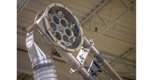
Figure 4 shows a photo of an installation of a continuous LP flash dryer with two ring Venturis. The feed auger is on the right in the photo.
See Figure 4
Pilot Plant
At the Aveka Manufacturing facility in Fredericksburg, IA, a continuous low-pressure (LP) flash drying pilot system has been installed to test, analyze, and pilot industrial products (Figure 5). The product is loaded into a hopper and can then be fed with the volumetric feeding system into the LP flash dryer with a controlled throughput rate. The needed airflow and operating parameters can be maintained, monitored and adjusted with a blower, airlocks, exhaust fan, and process air heater. The separation of the solids is performed in a horizontal cyclone and a baghouse. The LP flash dryer unit can be monitored for proper pressure/vacuum and temperature settings to achieve optimal processing capabilities.
See Figure 5
Applications for the Continuous LP Flash Drying Technology
If the drying material can be freely fed into the system and the moisture can be reached the LP flash drying technology can be applied. Some drying products like harder filter or centrifuge cakes may require pre-conditioning through a milling device. The LP flash drying system can efficiently replace the main dryer in a process or serve as a pre- or add-on dryer in a solid manufacturing process. As a pre-dryer the system can e.g. remove the reachable moisture very efficiently. The product bounded moisture, where more retention time is needed, can then be removed in a second drying step with e.g. a fluidized bed dryer or a drum dryer. As an add-on dryer the LP flash system can increase the capacity of conventional dryers, such as conventional spray drying systems.
Figure 6 and 7 show some examples for feedstock applications of the continuous LP flash drying technology.
See Figures 6 and 7
Benefits of a Continuous LP Flash Drying System
High drying efficiency: In conventional drying processes the drying material (both solids and moisture) require temperature addition to transfer the liquid into vapor and heat energy needs to be applied. In a low-pressure flash drying system, the surrounding pressure is reduced and adjusted to below the vapor pressure of the liquid without significantly raising the temperature of the drying feedstock. In this operating environment the moisture cannot exist in a liquid state and can be separated as vapor in the following process steps with almost no temperature increase.
Figure 8 shows a comparison of a fluidized bed dryer and a continuous LP flash dryer with similar throughput for the drying of wheat mids from 13% moisture to less than 7%. The LP flash dryer needs only 63% of the energy input compared with the fluidized bed dryer.
See Figure 8
The table in Figure 9 shows the range of energy consumption of different dryers. The energy consumption per evaporated pound of water for continuous LP flash drying systems is significantly lower.
See Figure 9
Improved product quality: The lower drying temperature allows for a much gentler drying process. As an example, for DDGS (dry distiller grain solids) overheating causes darkening, burned flavor and smell. The cause is the Maillard reaction of amino acids with reducing sugars above 280°F rendering amino acids undigestible. With the continuous LP flash drying technology, the drying temperature can be adjusted significantly below 280°F (Figure 10).
See Figure 10
Less environmental impact: The low drying temperature and extremely low residence time in continuous LP flash dryers is also beneficial for the environmental impact of the drying process. The VOC concentration in conventional dryers depends on the nature of the feed product, the drying temperature and the residence time.
Process simplification: With the continuous LP flash drying technology an effective process simplification can be realized. As an example, the drying of sulfate crystals is shown. In an existing production process 12,000 tn/year dry sulfate crystals (1-2 mm) were produced in a 24/7 operation. The mechanical solid-liquid-separation was done in a centrifuge and the drying in fluidized bed dryers. Because the product was becoming quite warm during the drying step it had to be cooled in a secondary fluidized bed to avoid caking. The particle transport was done in a high maintenance consuming bucket elevator system. With a continuous LP flash dryer, it was possible to replace the fluidized bed, the cooler, and the bucket elevator (see Figure 11).
See Figure 11
The goal to allow a moisture after drying of less the 0.5% and to maintain the product temperature below 160°F was more than achieved with final temperatures below 120°F. In addition, energy savings of $70,000/year were realized.
Reduced footprint: The simplified and straight forward continuous LP flash drying process allows a simple and reduced footprint. Figure 12 shows a phosphate production process with the former conventional cone dryer and the replacement with a LP flash dryer.
See Figure 12
The simplified process and reduced footprint also allow for reduced maintenance and investment cost.
In parallel and in series configurations of continuous LP flash dryers: To achieve higher throughputs under optimal process parameters two or more LP flash dryers can be installed parallel (Figure 13). If the required moisture level is not achieved in one flash drying step two or more dryers can also be installed in series (Figure 14). In addition, both configurations can also be combined to achieve optimal process conditions.
See Figures 13 and 14
Herbert H. Riemenschneider, Prof. Dr.-Ing., is VP Innovation & Technology, Stephen T. Sewell is CEO, and John Hogan is CIO, Flash Rockwell Technologies. For more information on implementing a continuous flash drying system, contact Flash Rockwell Technologies at 251-605-9595 or [email protected], or visit www.flashrockwell.com.
[1] Kemp, I. C., Energy Use in Industrial Drying, UK Department of Energy
[2] Phase diagram of water
[3] Mujumdar A., Recent Innovations in Drying Technologies, August 2016
For related articles, news, and equipment reviews, visit our Drying & Thermal Solids Processing Equipment Zone
Click here for a List of Drying & Thermal Solids Processing Equipment Manufacturers
You May Also Like
Editor's Choice

.svg?width=800&auto=webp&quality=80&disable=upscale)